5
POWER SUPPLY MODULE
5.3 Names of Parts and Settings
5 - 29
1
OVERVIEW
2
SYSTEM
CONFIGURATION
3
GENERAL
SPECIFICATIONS
4
HARDWARE
SPECIFICATIONS OF
THE CPU MODULE
5
POWER SUPPLY
MODULE
6
BASE UNIT AND
EXTENSION CABLE
7
MEMORY CARD AND
BATTERY
8
CPU MODULE START-
UP PROCEDURES
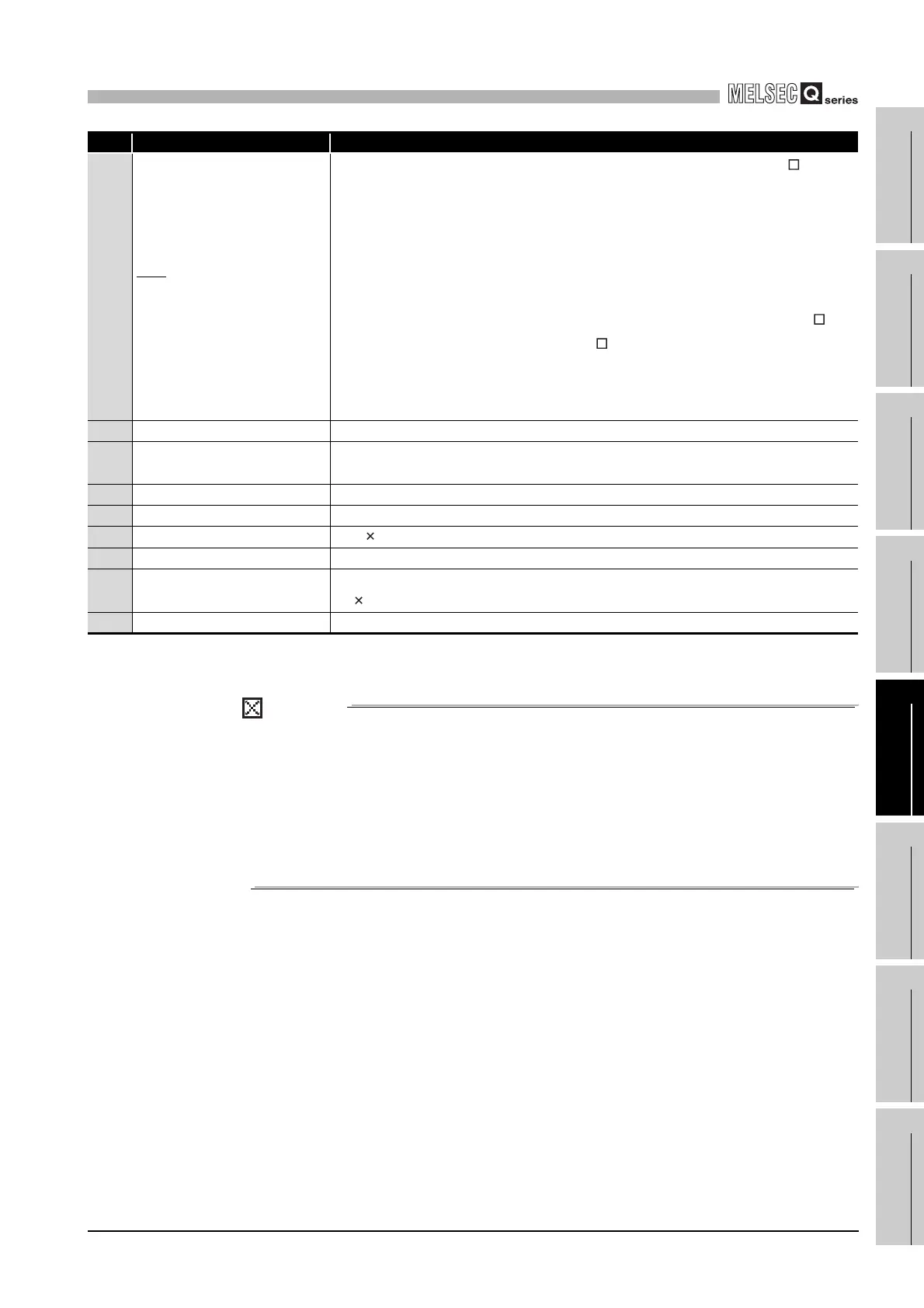
*: Although the "POWER" LED lights up in red for a moment immediately after the power supply is turned on or off, redun-
dant power supply modules is not faulty.
POINT
1. Q64RP automatically switches the input range 100/200VAC.
Therefore, it is not compatible with the intermediate voltage (133 to 169VAC).
The CPU module may not work normally if the above intermediate voltage is
applied.
2. Supply power to redundant power supply modules from separate power
sources (a redundant power supply system).
3. Ensure that the earth terminals LG and FG are grounded.
4) ERR terminals
<When power supply is mounted on redundant power main base unit (Q3 RB)>
• Turned ON when the system on the redundant power main base unit operates
normally.
• Turned OFF (open) when the Q64RP fails, the AC power supply is not input, a
CPU module stop error (including a reset) occurs, or the fuse is blown.
• Turned OFF (open) when a stop error occurs in any of the CPU modules in a
multiple CPU system.
<When power supply is mounted on redundant power extension base unit (Q6 RB)
or redundant type extension base unit (Q6 WRB)>
• Turned ON when the Q64RP operates normally.
• Turned OFF (open) when the Q64RP fails, the AC power supply is not input, or the
fuse is blown.
5) FG terminal Ground terminal connected to the shield pattern of the printed circuit board.
6) LG terminal
Grounding for the power supply filter. The potential of Q64RP terminal is 1/2 of the
input voltage.
7) Power input terminals Connect direct current of 24 VDC with the power input terminal.
8) Power input terminals Power input terminals and connected to a 100VAC/200VAC power supply.
9) Terminal screw
M3.5 7 screw
10) Terminal cover Protective cover of the terminal block
11) Module fixing screw hole
Screw hole for fixing a module to the base unit.
M3 12 screw (user-prepared) (Tightening torque : 0.36 to 0.48N•m)
12) Module loading lever Used to mount a module on the base unit.
No. Name Application
 Loading...