6
BASE UNIT AND EXTENSION CABLE
6.1 Base Unit
6.1.4 Guideline for Use of Extension Base Units
6 - 19
1
OVERVIEW
2
SYSTEM
CONFIGURATION
3
GENERAL
SPECIFICATIONS
4
HARDWARE
SPECIFICATIONS OF
THE CPU MODULE
5
POWER SUPPLY
MODULE
6
BASE UNIT AND
EXTENSION CABLE
7
MEMORY CARD AND
BATTERY
8
CPU MODULE START-
UP PROCEDURES
The voltage supplied to the "IN" connector of the Q5 B reaches 4.75 VDC or later on the
condition that the voltage drop (V) at the extension cable between the main base unit and
Q5 B is 0.15 VDC or lower.
(3) When the GOT is bus-connected
(a) Selection condition
4.75VDC or later should be supplied to the "IN" connector of the Q5 B.
(b) How to calculate voltage to "IN" connector
The 5VDC output voltage of the power supply module on the main base unit is set
to at least 4.90VDC.
Therefore, the Q5 B can be used if the voltage drop is 0.15VDC or lower
(4.9VDC -4.75VDC = 0.15VDC).
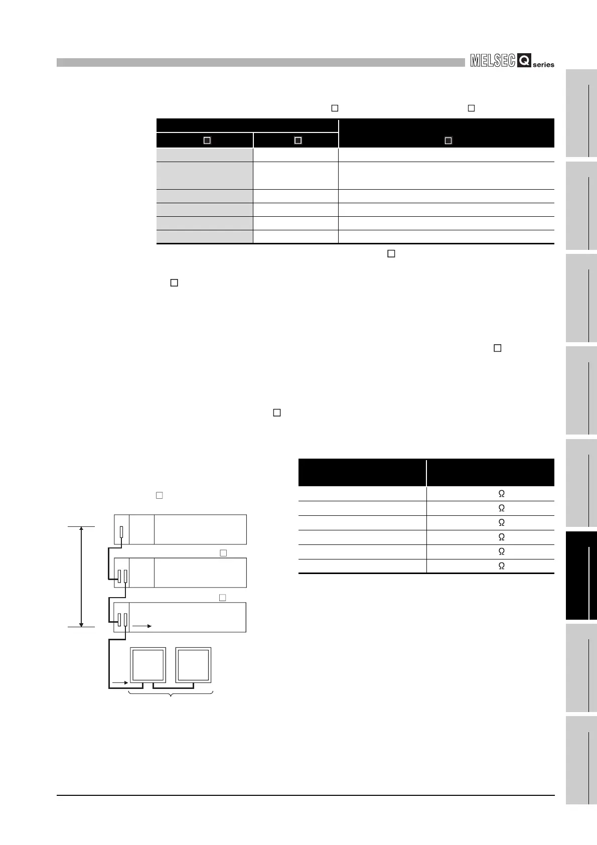
Table6.22 List for Calculating Voltage Drops Occurring at Extension Cables
when connecting Q6 B between main base unit and Q5 B
Position of extension base unit Voltage drop caused by extension cable from the
main base unit to the Q5 B IN connector (V)
Q6 B Q5 B
Extension stage 1 Extension stage 2 V=(R1+R2)I1
Extension stage 1,
Extension stage 2
Extension stage 3 V=(R1+R2+R3)I2
Extension stage 1 to 3 Extension stage 4 V=(R1+R2+R3+R4)I3
Extension stage 1 to 4 Extension stage 5 V=(R1+R2+R3+R4+R5)I4
Extension stage 1 to 5 Extension stage 6 V=(R1+R2+R3+R4+R5+R6)I5
Extension stage 1 to 6 Extension stage 7 V=(R1+R2+R3+R4+R5+R6+R7)I6
Table6.23 Extension Cable Conductor Resistance
Extension Cable Type
Extension Cable Conductor
Resistance
QC05B
0.044
QC06B
0.051
QC12B
0.082
QC30B
0.172
QC50B
0.273
QC100B
0.530
Diagram 6.11 System Configuration
R1
V
R2
Im
GOT GOT
Number of GOTs connected : Max. 5units
Power
supply
module
Power
supply
module
Extension
stage 1
I1
Extension
stage 2
Extension
stage 3
[When the Q5 B is connected to Extension stage 2.]
Main base unit
Extension base unit (Q6 B)
Extension base unit (Q5 B)
 Loading...