6 - 20
6.1 Base Unit
6.1.4 Guideline for Use of Extension Base Units
6
BASE UNIT AND EXTENSION CABLE
The voltage supplied to the "IN" connector of the Q5 B reaches 4.75 VDC or later on the condition that the
voltage drop (V) at the extension cable between the main base unit and Q5 B is 0.15 VDC or lower.
POINT
When connecting GOT by extension cable that is 13.2 m (43.31ft) or longer, the
bus extension connector box A9GT-QCNB is required.
Since the A9GT-QCNB is supplied with 5VDC from the power supply module
loaded on the main base unit, 30mA must be added to "Im" as the current
consumption of the A9GT-QCNB.
For details of the method for GOT bus connection, refer to the manual below.
GOT-A900 Series User's Manual (Connection)
GOT1000 Series Connection Manual
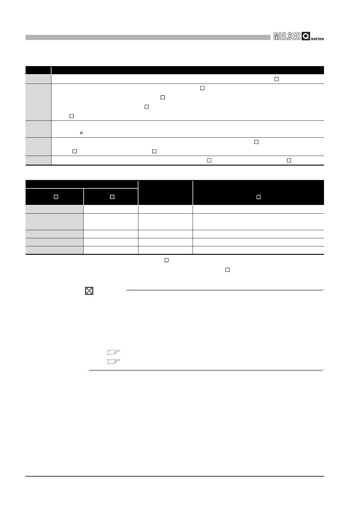
Table6.24 Symbol explanation
Symbol Description
V
Voltage drop at the extension cable between the main base unit and extension base unit (Q5 B)
In
5VDC current consumption when the extension base unit (Q5 B) is used as Extension n+1, n = 1 to 5, n:
Extension No. of the extension base unit (Q6 B) connected
(Sum total of current consumed by Q5 B and currents consumed by I/O, intelligent function modules loaded on
the Q5 B)
Im
5VDC current consumption of the GOT (current consumption per GOT is 255mA)
• Im = 255 c (c: Number of GOTs connected (c: 1 to 5))
Rn
Extension cable resistance between the main base unit and extension base unit (Q6 B) or the extension base
unit (Q6 B) and extension base unit (Q6 B)
R
n+1
Extension cable resistance between the extension base unit (Q6 B) and extension base unit (Q5 B)
Table6.25 List of calculated voltage drop caused by the extension in bus connection of GOT
Position of extension base unit No. of stages for
GOT bus
connection
Voltage drop caused by extension cable from the
main base unit to the Q5 B IN connector (V)
Q6 B Q5 B
Extension stage 1 Extension stage 2 Extension stage 3 V=(R1+R2)(I1+Im)
Extension stage 1,
Extension stage 2
Extension stage 3 Extension stage 4 V=(R1+R2+R3)(I2+Im)
Extension stage 1 to 3 Extension stage 4 Extension stage 5 V=(R1+R2+R3+R4)(I3+Im)
Extension stage 1 to 4 Extension stage 5 Extension stage 6 V=(R1+R2+R3+R4+R5)(I4+Im)
Extension stage 1 to 5 Extension stage 6 Extension stage 7 V=(R1+R2+R3+R4+R5+R6)(I5+Im)
 Loading...