7
MEMORY CARD AND BATTERY
7.2 Battery (Q6BAT, Q7BAT, Q8BAT)
7.2.2 Installation of Battery
7 - 18
1
OVERVIEW
2
SYSTEM
CONFIGURATION
3
GENERAL
SPECIFICATIONS
4
HARDWARE
SPECIFICATIONS OF
THE CPU MODULE
5
POWER SUPPLY
MODULE
6
BASE UNIT AND
EXTENSION CABLE
7
MEMORY CARD AND
BATTERY
8
CPU MODULE START-
UP PROCEDURES
POINT
• Fix the Q8BAT connection cable using a clamp.
Failure to do so may cause damage of the Q8BAT connection cover,
connector or cable due to unintentional swinging and shifting or
accidental pull of the cable.
• Ensure the bending radius of 10mm (0.39 inch) or more for the Q8BAT
connection cable.
If the bend radius is less than 10mm, a malfunction may occur due to
characteristic deterioration, wire breakage.
• For details of the module mounting position, refer to the following:
Section 10.3.2
• When mounthing the Q8BAT for the Universal model QCPU, use the
connection cable whose connector part displays “A”.
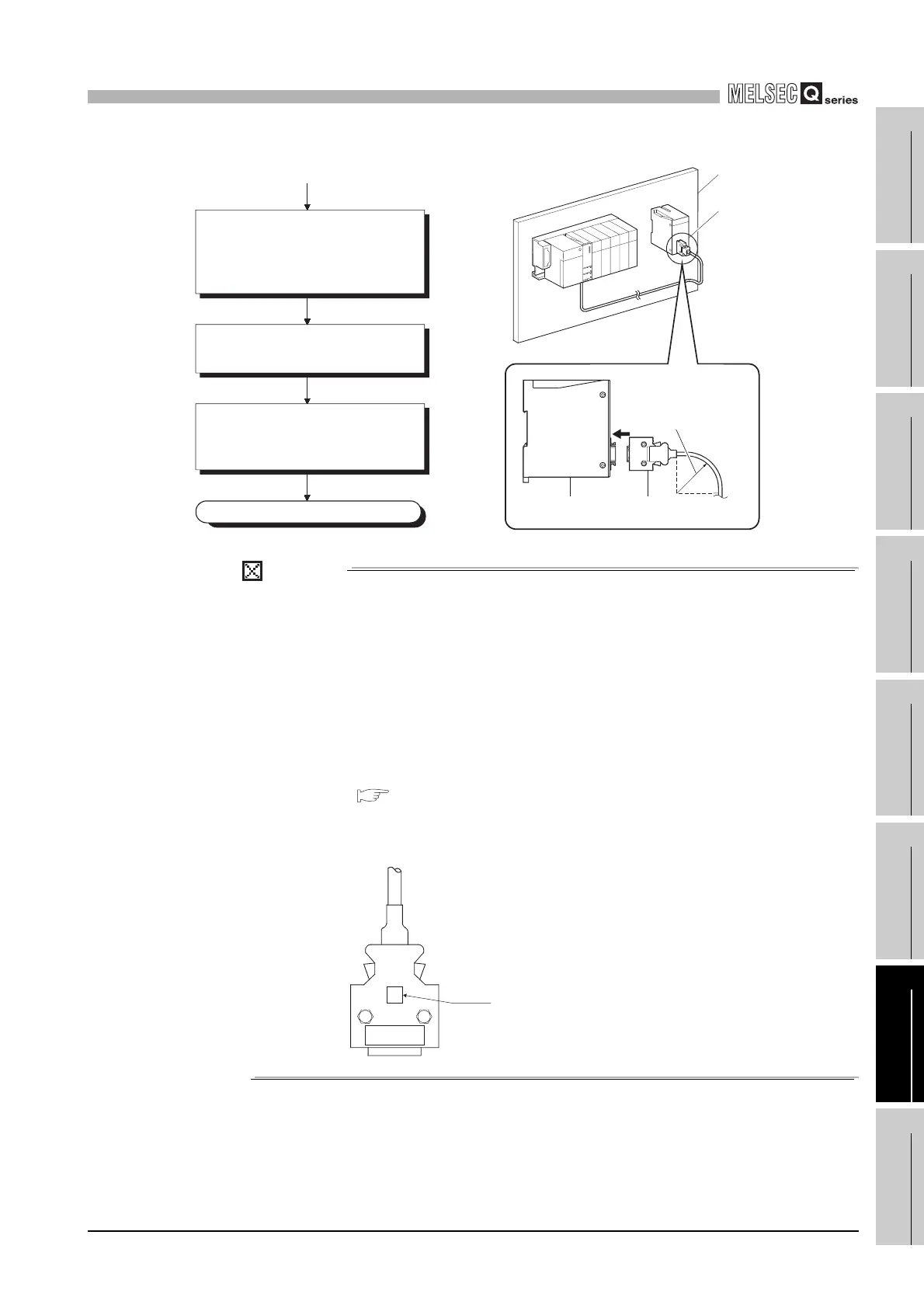
Mount the CPU module onto the main
base unit, so that the Q8BAT
connection cable connected to the
CPU module will not interfere with the
other devices.
Fix the Q8BAT onto the control panel.
(Screws or DIN rail is applicable.)
(From previous page)
Attach the connector of Q8BAT
connection cable to the Q8BAT while
confirming the orientation of the
connector.
Completed
Q8BAT
Control panel
Q8BAT
connection cable
Q8BAT
R (bending radius)
10mm (0.39 inch)
or more
A
Sticke
 Loading...