10 - 24
10.3 Module Installation
10.3.3 Installation and removal of module
10
LOADING AND INSTALLATION
POINT
1. When mounting the module, always insert the module fixing projection into
the module fixing hole of the base unit.
At that time, securely insert the module fixing projection so that it does not
come off from the module fixing hole.
If the module is forcibly mounted without the latch being inserted, the module
connector and module will be damaged.
2. When using the programmable controller in a place where there is large
vibration or impact, screw the CPU module to the base unit.
Module fixing screw : M3 X 12 (user-prepared)
3. Do not mount/remove the module onto/from base unit or terminal block more
than 50 times (IEC 61131-2 compliant), after the first use of the product.
Failure to do so may cause the module to malfunction due to poor contact of
connector.
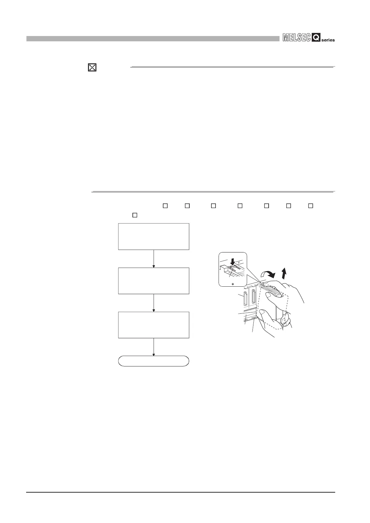
(b) Removal from Q3 B, Q3 SB, Q3 RB, Q3 DB, Q5 B, Q6 B, Q6 RB,
and Q6 WRB
* 1: If the module has two module fixing hooks on its top, push the two modules fixing projections on
the right and left of the module top simultaneously with your fingers until they stop.
Diagram 10.25 Module removal procedure
Completed
Unit/Module
Module
connector
Module fixing hole
Base unit
Push
Module fixing
hook
Lifting
1
Pull the module based on the
supporting point of module bottom
while pressing the module fixing
hook (*1).
While lifting the module, take off
the module fixing projection (*2)
from the module fixing hole.
Support the module with both
hands and securely press the
module fixing hook(*1) with your
finger.
 Loading...