10
LOADING AND INSTALLATION
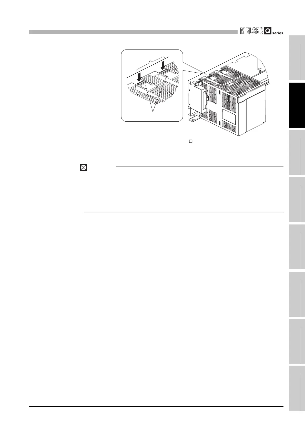
10.3 Module Installation
10.3.3 Installation and removal of module
10 - 25
9
EMC AND LOW
VOLTAGE
DIRECTIVES
10
LOADING AND
INSTALLATION
11
MAINTENANCE AND
INSPECTION
12
TROUBLESHOOTING APPENDICES INDEX
* 2: If the module has two fixing projections, remove the two module fixing projections on the right and
left of the module bottom from the module fixing holes.
POINT
When the module fixing screw is used, always remove the module by removing
the module fixing screw and then taking the module fixing projection off the
module fixing hole of the base unit.
Attempting to remove the module by force may damage the module fixing
projection.
Diagram 10.26 Q6 RP removal procedure
Push simultaneously
Module fixing projection
 Loading...