10 - 26
10.3 Module Installation
10.3.3 Installation and removal of module
10
LOADING AND INSTALLATION
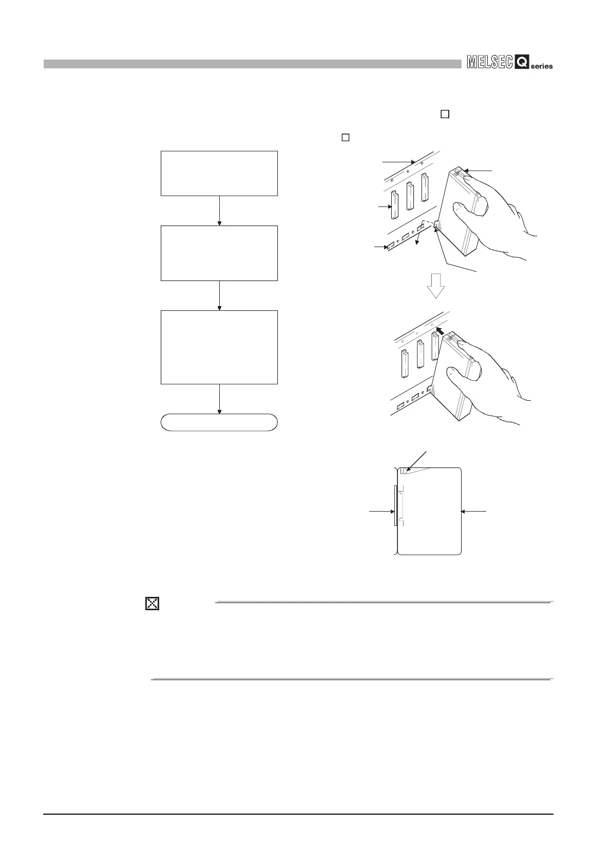
(2) Installation and removal of the module from QA1S6 B
(a) Installation of module on QA1S6 B
POINT
Make sure to install the module, with the module fixing projection inserted into the
module fixing hole, using the module fixing screws.
If the module is installed forcedly without the module fixing projections inserted,
the module connector and the module may be damaged.
Diagram 10.27 Module mounting procedure
Base unit
Module
connector
Module fixing
cutout
Unit/Module
module fixing
projection
Unit installation screw
Unit/Module
Base unit
Completed
Make sure that the
module is firmly inserted
in the base unit. Then,
secure it with the module
mounting screw.
Insert the module fixing
projections into the module
fixing hole in the base unit.
Using the module fixing hole as
a support, install the module
onto the base unit by pushing it
in the direction of arrow.
 Loading...