10
LOADING AND INSTALLATION
10.3 Module Installation
10.3.3 Installation and removal of module
10 - 27
9
EMC AND LOW
VOLTAGE
DIRECTIVES
10
LOADING AND
INSTALLATION
11
MAINTENANCE AND
INSPECTION
12
TROUBLESHOOTING APPENDICES INDEX
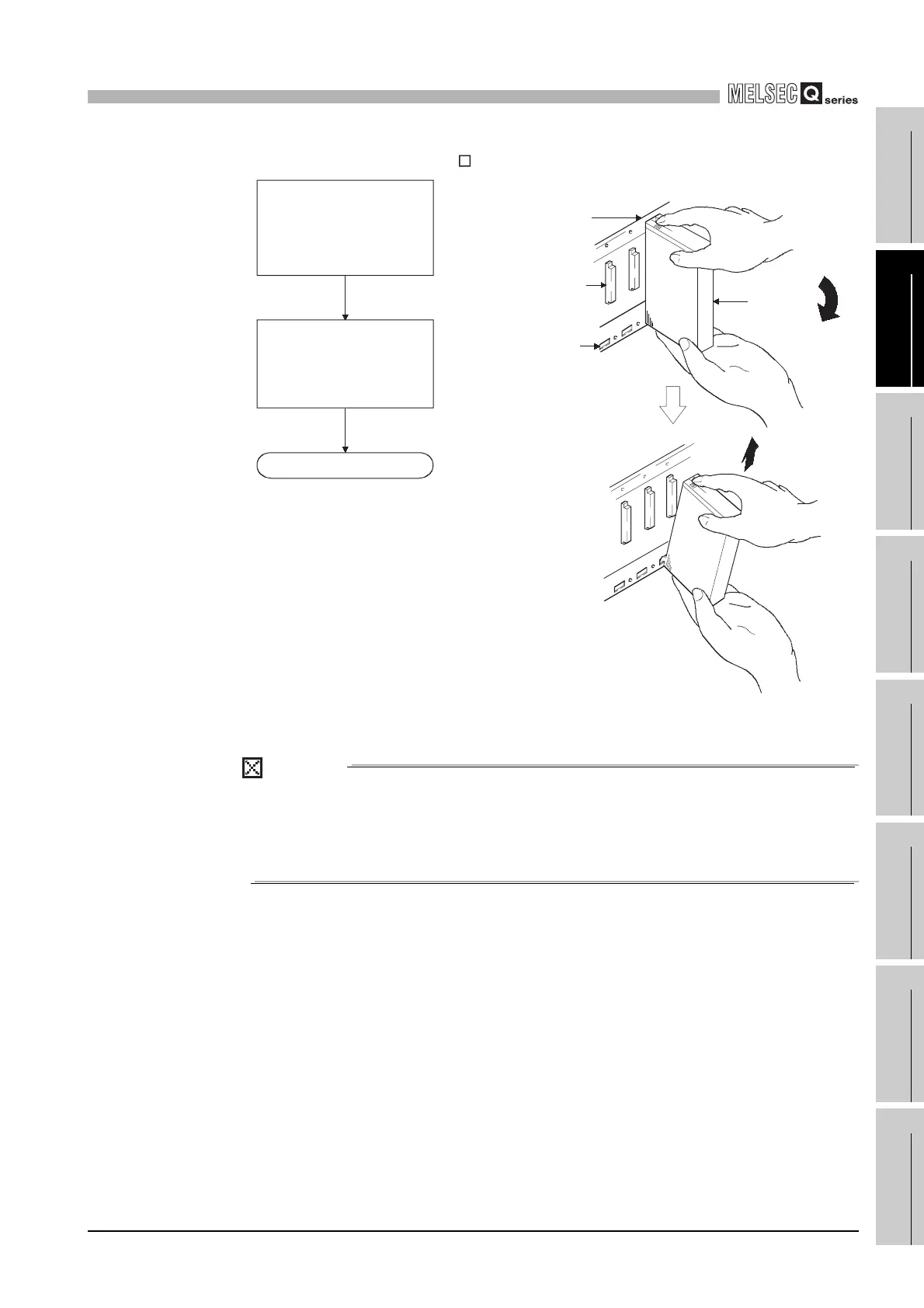
(b) Removal from QA1S6 B
POINT
To remove the module, make sure to remove the module fixing screws, and then
disengage the module fixing projection from the module fixing hole.
Attempting to remove the module by force may damage the module fixing
projection.
Diagram 10.28 Module removal procedure
Base unit
Unit/Module
Completed
Lift the module upwards
and remove the module
fixing projection from the
module fixing hole.
Remove the module
mounting screw, and
using the bottom of the
module as a support,
pull the top of the
module toward you.
Module connector
Module fixing cutout
 Loading...