10
LOADING AND INSTALLATION
10.6 Wiring
10.6.1 The precautions on the wiring
10 - 37
9
EMC AND LOW
VOLTAGE
DIRECTIVES
10
LOADING AND
INSTALLATION
11
MAINTENANCE AND
INSPECTION
12
TROUBLESHOOTING APPENDICES INDEX
This section describes the precautions for wiring power supply lines.
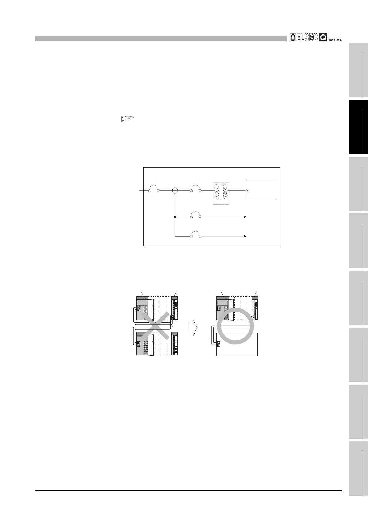
(1) Wiring power supply lines
• Wire the power supply lines for programmable controller, I/O devices, and motor
equipment separately as shown in Diagram 10.37.
• If there is much noise, such as lightning surge, connect an isolation transformer.
For details on the isolation transformer, refer to the following.
Section 9.1.6(3) Isolation transformer
• Taking rated current or inrush current into consideration when wiring the power
supply, be sure to connect a breaker or an external fuse that have proper blown
and detection.
When using a single programmable controller, a 10A breaker or an external fuse
are recommended for wiring protection.
• Do not connect the 24VDC outputs of two or more power supply modules in
parallel to supply power to one I/O module. Parallel connection will damage the
power supply modules.
• 100VAC, 200VAC and 24VDC wires should be twisted as dense as possible.
Connect the modules with the shortest distance.
Also, to reduce the voltage drop to the minimum, use the thickest wires possible
(maximum 2mm
2
).
• Do not bundle the 100VAC and 24VDC wires with, or run them close to, the main
circuit (high voltage, large current) and I/O signal lines (including common line).
Reserve a distance of at least 100 mm from adjacent wires.
Diagram 10.37 Power supply wiring diagram
Diagram 10.38 Cautions when connecting a power supply module
100VAC
200VAC
T1
Main
power supply
Relay
terminal block
I/O power supply
I/O equipment
Inside a control panel
Programmable
controller power
supply
Isolation
transformer
Programmable
controller
Motor power supply
Motor equipment
Power supply module I/O module
DC24V
DC24V
Power supply module I/O module
DC24V
External power supply
 Loading...