12 - 6
12.2 Troubleshooting
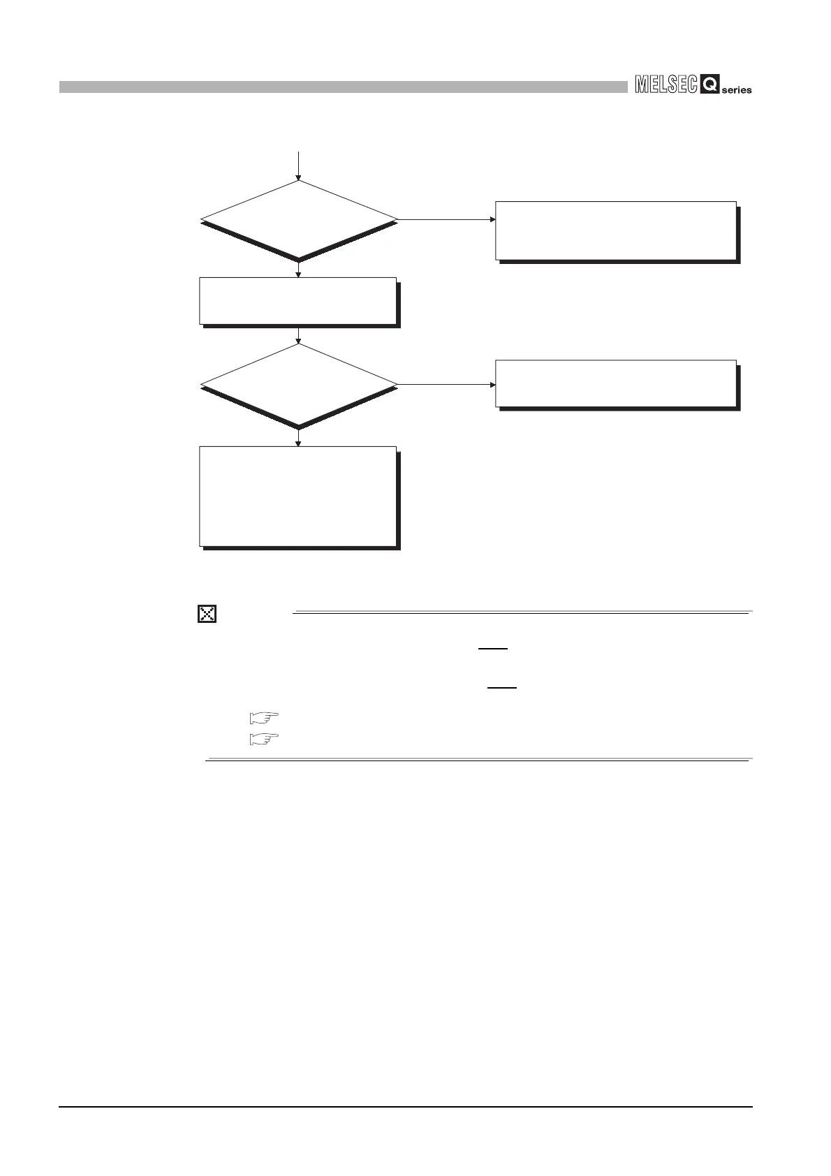
12.2.2 Flowchart for when the ERR terminal (negative logic) is turned off (opened)
12
TROUBLESHOOTING
POINT
If a CPU module stop error occurs during use of two redundant power supply
modules, the error is output from the ERR
terminals of the two redundant power
supply modules.
Refer to the following for details of the ERR
terminal.
Section 5.2.1 Power supply module specification list
Section 10.6.2 Wring of power supply module
Diagram 12.2 Flowchart for when the ERR terminal is turned off
Check the sum of internal current
consumptions of the modules that
comprise the system.
Hardware fault
Execute operation checks in due order,
starting with the minimum system.
For the module that does not operate,
please contact your local nearest
Mitsubishi or representative, explaining
a detailed description of the problem.
Off
Reexamine the system configuration to make the
total current less than the rated current consumption
of one power supply module.
On (green)
The base unit that includes the corresponding
power supply module is faulty.
(Change it for a normal base unit.)
Yes
No
Does the total
current exceed the rated
current consumption of one power
supply module?
How is the "POWER"
LED of the power supply
module?
(From previous page)
 Loading...