12
TROUBLESHOOTING
12.2 Troubleshooting
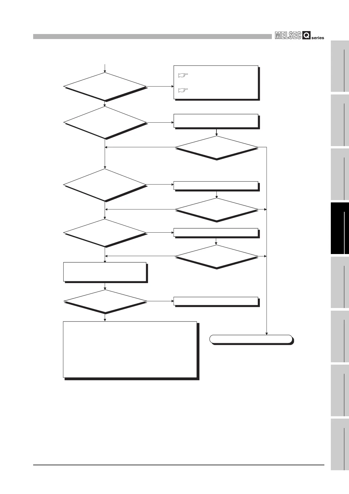
12.2.25 Flowchart for when the CPU cannot communicate with the GX Developer
12 - 35
9
EMC AND LOW
VOLTAGE
DIRECTIVES
10
LOADING AND
INSTALLATION
11
MAINTENANCE AND
INSPECTION
12
TROUBLESHOOTING APPENDICES INDEX
Connect the extension cable properly.
Hardware fault of power supply module.
Completed
NO
YES
NO
YES
NO
YES
NO
NO
YES
RESET position
How is the "POWER" LED
of the power supply module?
NO
Check the wiring and power on all
the power supply modules.
YES
Is the extension
cable connected properly?
(Isn't IN connected to
IN or OUT connected
to OUT?)
Is the CPU module
RESET/L. CLR switch in
the neutral position?
Other than RESET position
Cancel the RESET.
YES
NO
YES
Can the CPU communicate
with the GX Developer?
Can the CPU communicate
with the GX Developer?
Can the CPU communicate
with the GX Developer?
Can the CPU communicate
with the GX Developer?
(When off)
(When on (red))
Flowchart for when
the "POWER" LED turns off.
Flowchart for when
the "POWER" LED turns on (red).
Are all the power
supply modules powered on?
Is the wiring of the power supply
module correct?
A hardware fault may have occurred in any of the following modules.
1) CPU module
2) Main base unit, extension base unit
3) Extension cable
4) I/O Module (If one is installed)
5) Interlligent function module (If one is installed)
6) Network module (If one is installed)
Perform operations in due order, starting with the minimum system
where the power supply module and CPU module are mounted on the
main base unit.
If the module will not work, please consalt your local nearest Mitsubishi
or representative, explaining a detailed discription of the problem.
(From previous page)
Replace the power supply module and
confirm that the "POWER" LED is turned
on green.
Section 12.2.5
Section 12.2.6
 Loading...