12
TROUBLESHOOTING
12.4 Module Change during System Operation
12.4.1 Online module change
12 - 251
9
EMC AND LOW
VOLTAGE
DIRECTIVES
10
LOADING AND
INSTALLATION
11
MAINTENANCE AND
INSPECTION
12
TROUBLESHOOTING APPENDICES INDEX
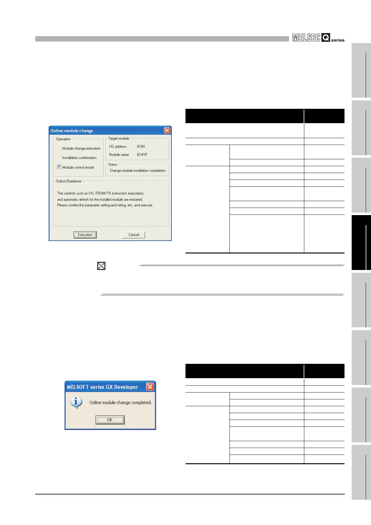
12)After mounting the module, click the "Execution" button.
(Table12.17 shows the communication status with the target module for online
module change when the following screen (refer to Diagram 12.27) is
displayed.)
POINT
When the initial settings of the intelligent function module have been made by GX
Configulator, the set data are written to the intelligent function module.
13)Click the "Execution" button to start control.
14)The "Online module change completed" screen appears.
(Table12.18 shows the communication status with the target module for online
module change when the following screen (refer to Diagram 12.28) is
displayed.)
Table12.17 Communication status with the module
Target module, item
Executed/Not
executed
Input module refresh
Not executed
(Data held)
Output module refresh Not executed
I/O hybrid module
Input refresh
Not executed
(Data held)
Output refresh Not executed
Intelligent function
module
Input refresh Executed
Output refresh Executed
FROM/TO instruction No processing
Instruction using intelligent
function module device
No processing
Intelligent dedicated instruction No processing
Intelligent automatic refresh No processing
Buffer memory batch monitor Executed
Diagram 12.27 Online module change screen
Table12.18 Communication status with the module
Target module, item
Executed/Not
executed
Input module refresh Executed
Output module refresh Executed
I/O hybrid module
Input refresh Executed
Output refresh Executed
Intelligent function
module
Input refresh Executed
Output refresh Executed
FROM/TO instruction Executed
Instruction using intelligent
function module device
Executed
Intelligent dedicated instruction Executed
Intelligent automatic refresh Executed
Buffer memory batch monitor Executed
Diagram 12.28 Online module change screen
 Loading...