2
SYSTEM CONFIGURATION
2.1 System Configuration
2.1.1 System Configuration for Single CPU System
2 - 6
1
OVERVIEW
2
SYSTEM
CONFIGURATION
3
GENERAL
SPECIFICATIONS
4
HARDWARE
SPECIFICATIONS OF
THE CPU MODULE
5
POWER SUPPLY
MODULE
6
BASE UNIT AND
EXTENSION CABLE
7
MEMORY CARD AND
BATTERY
8
CPU MODULE START-
UP PROCEDURES
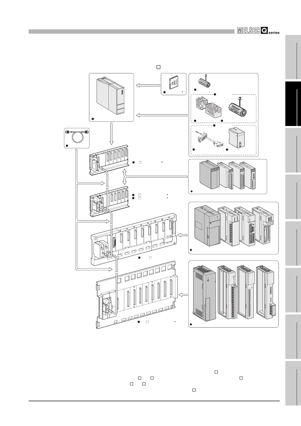
(2) System configuration using the High Performance model QCPU
(a) If the main base unit (Q3 B) is used
* 1: One memory card can be installed.
Select a memory card from SRAM card, Flash card, and ATA card according to the application
and capacity.
With commercial memory cards, the operation is not assured.
* 2: As a power supply module, use the Q series power supply module.
The slim type power supply module and the redundant power supply module are not available for
the power supply module.
* 3: The Q series power supply module is not required for the Q5 B extension base unit.
* 4: The QA6ADP+A5 B/A6 B is available. However, when using the QA1S6 B, the
QA6ADP+A5 B/A6 B cannot be connected.
Diagram 2.5 System configuration when Q3 B is used
Extension cable
Battery for QCPU (Q7BAT)
Q7BAT-SET
Battery holder
Battery for QCPU (Q6BAT)
Q8BAT-SET
Q8BAT connection cable
Memory card
1
High Performance model QCPU
Q3 B main base unit
2
Q6 B extension base unit
Q5 B extension base unit
2
3
4
QA1S6 B extension base unit
QA6 B extension base unit
Power supply module, I/O module, Intelligent function module of the AnS Series
Power supply module/I/O module/Intelligent function module
Battery for QCPU
(Q8BAT)
Power supply module, I/O module, Special function module of the A Series
 Loading...