2
SYSTEM CONFIGURATION
2.1 System Configuration
2.1.1 System Configuration for Single CPU System
2 - 14
1
OVERVIEW
2
SYSTEM
CONFIGURATION
3
GENERAL
SPECIFICATIONS
4
HARDWARE
SPECIFICATIONS OF
THE CPU MODULE
5
POWER SUPPLY
MODULE
6
BASE UNIT AND
EXTENSION CABLE
7
MEMORY CARD AND
BATTERY
8
CPU MODULE START-
UP PROCEDURES
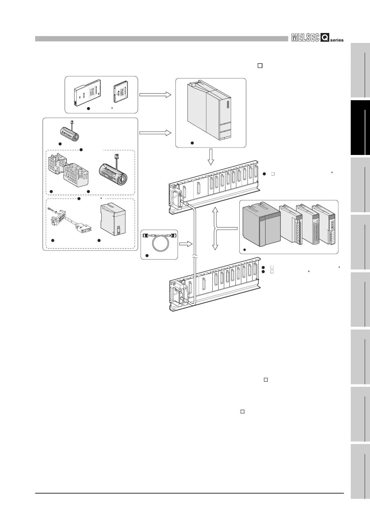
(b) When the redundant power main base unit (Q3 RB) is used
* 1: One memory card can be installed.
Select a memory card from SRAM card, Flash card, and ATA card according to the application
and capacity.
With commercial memory cards, the operation is not assured.
* 2: Use the redundant power supply module for the power supply module.
The redundant power supply module can use the both Q63RP and Q64RP together with one
redundant base unit.
The Q series power supply module and the slim type power supply module are not available for
the power supply module.
* 3: The Q series power supply module is not required for the Q5 B extension base unit.
* 4: When using the Q8BAT-SET for the Universal model QCPU, use the connection cable whose
connector part displays "A".
For details of connector part of a connection cable, refer to Section 7.2.2.
Diagram 2.13 System configuration when Q3 RB is used
Universal model QCPU
Extension cable
Q3 RB redundant power main base unit
2
Q6 RB redundant power extension base unit
Q5 B extension base unit
2
3
Redundant power supply module/I/O module/Intelligent function module
Battery holder Battery for QCPU (Q7BAT)
Battery for QCPU (Q6BAT)
Q7BAT-SET
Battery for QCPU
(Q8BAT)
Q8BAT-SET
Q8BAT connection cable
4
Memory card
1
 Loading...