4 - 3
4 INSTALLATION AND WIRING
4.1.2 Instructions for mounting the modules
When mounting the Motion controller, base unit to an enclosure or similar, fully
consider its operability, maintainability and environmental resistance.
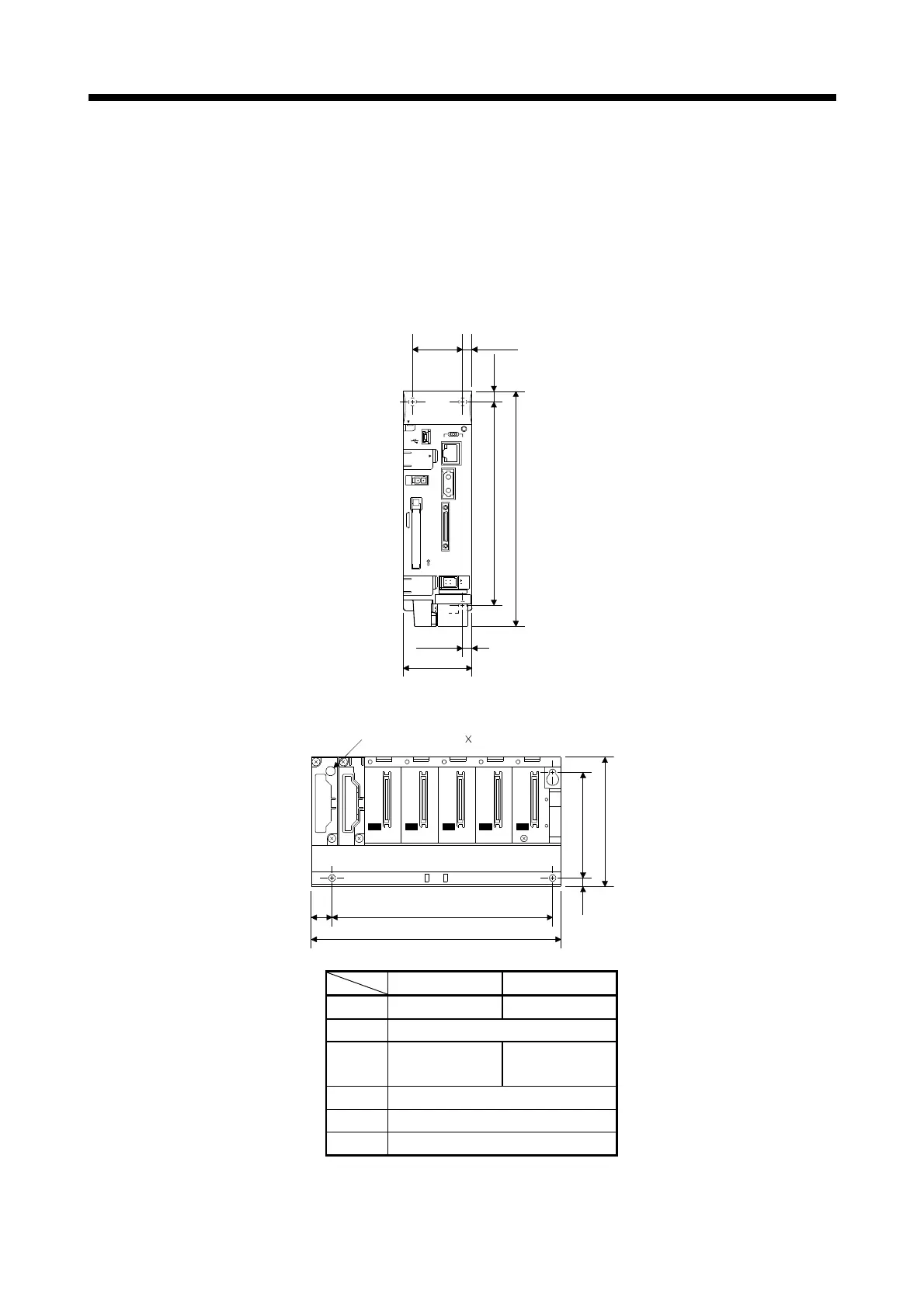
(1) Fitting dimensions
(a) Motion controller
[Unit: mm (inch)]
USB
POWER
STOPRESET RUN
PERI PHE RAL I/ F
CN1
EXT. IO
24VDC
OUT
FRONT
CARD
RS-232
EMI
EJECT
MITSUBISHI Q170MCPU
MODE
RUN
ERR.
USER
BAT.
BOOT
PULL
178(7.01)
154(6.06)
8
7(0.28)
52(2.05)
38(1.50) 7(0.28)
(0.31)
(b) Base unit
Ws2
W
Hs2
H
IN
Ws1
Hs1
I/O0 I/O1 I/O2 I/O3 I/O4
OUT
4-fixing screw (M4 14)
Q52B Q55B
W 106 (4.17) 189 (7.44)
Ws1 15.5 (0.61)
Ws2
83.5 ± 0.3
(3.29 ± 0.01)
167 ± 0.3
(6.57 ± 0.01)
H 98 (3.86)
Hs1 7 (0.28)
Hs2 80 ± 0.3 (3.15 ± 0.01)
[Unit: mm (inch)]

 Loading...
