2 - 34
2 SYSTEM CONFIGURATION
2.5.3 Q172DLX Servo external signals interface module
Q172DLX receives external signals (servo external signals) required for positioning
control.
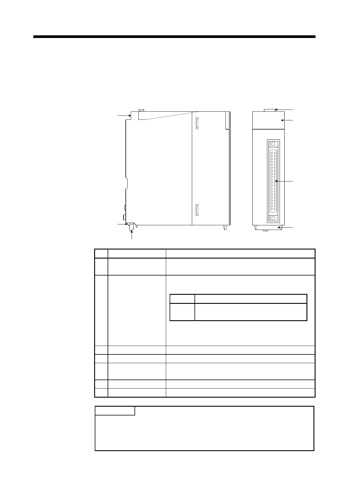
(1) Q172DLX name of parts
Q172DLX
Q172DLX
CTRL
2)
1)
3)
7)
6)
5)
4)
No. Name Application
1) Module fixing hook
Hook used to fix the module to the base unit.
(Single-motion installation)
Display the servo external input status from the external
equipment.
LED Details
0 to 1F
Display for servo external signal input status of
each axis.
2) Mode judging LED
The proximity dog/speed-position switching signal (DOG/
CHANGE) does not turn ON without setting Q172DLX in the
system setting.
3) CTRL connector The servo external signal input connector of each axis.
4) Module mounting lever Used to install the module to the base unit.
5)
Module fixing screw
hole
Hole for the screw used to fix to the base unit.
(M3×12 screw : Purchase from the other supplier)
6) Module fixing projection Projection used to fix to the base unit.
7) Serial number display Display the serial number described on the rating plate.
POINT
Mode judging LED of the proximity dog/speed-position switching signal (DOG/
CHANGE) turns ON at the following conditions.
• Q172DLX is set on the system setting of MT Developer2.
• The proximity dog/speed-position switching signal (DOG/CHANGE) is input.

 Loading...
