14 - 3 14 - 3
MELSEC-Q
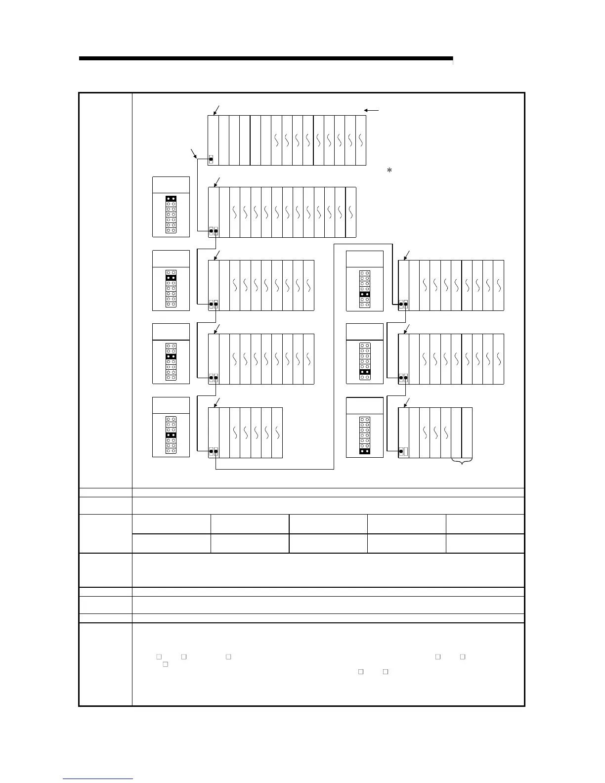
14 SYSTEM CONFIGURATION OF MULTIPLE PLC SYSTEM
System
configuration
4 extension
stages
2 extension
stages
1 extension
stages
6 extension
stages
7 extension
stages
5 extension
stages
3 extension
stages
100
11F
Power supply module
20
3F
40
5F
60
7F
80
9F
A0
BF
C0
DF
E0
FF
01234567891011
Main base unit (Q312B)
Slot No.
C P U 1
OUT
00
1F
C P U 2
C P U 3
C P U 4
2A0
2BF
2C0
2DF
2E0
2FF
Power supply module
1C0
1DF
1E0
1FF
200
21F
220
23F
240
25F
260
27F
280
29F
13 14 15 16 17 18 19 20 21 22 23
Extension base unit (Q612B)
IN
1A0
1BF
OUT
180
19F
12
Power supply module
340
35F
360
37F
380
39F
3A0
3BF
3C0
3DF
3E0
3FF
25 26 27 28 29 30 31
Extension base unit (Q68B)
IN
320
33F
OUT
300
31F
24
Power supply module
440
45F
460
47F
480
49F
4A0
4BF
4C0
4DF
4E0
4FF
33 34 35 36 37 38 39
Extension base unit (Q68B)
IN
420
43F
OUT
400
41F
32
Power supply module
540
55F
560
57F
580
59F
41 42 43 44
Extension base unit (Q65B)
IN
520
53F
OUT
500
51F
40
Power supply module
5E0
5FF
600
61F
620
63F
640
65F
660
67F
680
69F
46 47 48 49 50 51 52
Extension base unit (QA1S68B)
IN
5C0
5DF
OUT
5A0
5BF
45
Power supply module
6E0
6FF
700
71F
720
73F
740
75F
760
77F
780
79F
54 55 56 57 58 59 60
Extension base unit (QA1S68B)
IN
6C0
6DF
OUT
6A0
6BF
53
Power supply module
62 63
Extension base unit (QA1S65B)
IN
OUT
61
Prohibit
When module is installed,
an error occurs.
The figure shows the configuration
when 32-I/O modules are mounted
to each slot.
Extension cable
Prohibit
160
17F
140
15F
120
13F
Number of CPU CPU1: PLC No.1, CPU2: PLC No.2, CPU3: PLC No.3, CPU4: PLC No.4
Maximum number
of extension stages
7 extension stages
Module count setting for
the multiple PLC setting
1234
Maximum number
of mounted I/O
modules
Number of module
mounted
64 modules 63 modules 62 modules 61 modules
Maximum
number of
occupied I/O
points
4096
Main base units Q33B, Q35B, Q38B, Q312B
Extension base
units
Q52B, Q55B, Q63B, Q65B, Q68B, Q612B, QA1S65B, QA1S68B
Extension cables QC05B, QC06B, QC12B, QC30B, QC50B, QC100B
Notes
(1) A maximum of 7 extension base units can be used.
(2) Do not use extension cable longer than 13.2 m (43.28 feet).
(3) When using an extension cable, it should not be connected to or allowed to come close to the main circuit (high voltage and large current).
(4) When setting the number of extension stages, set the number in ascending order to avoid setting the same number repeatedly.
(5) If Q5
B / Q6 B and QA1S6 B are to be mounted on the same extension base unit, be sure to connect Q5 B / Q6 B at first and then
QA1S6
B.
Make the setting of the number of levels of an extension base unit, starting with Q5
B / Q6 B in a descending order.
(6) Connect an extension cable between the OUT connector of an extension base unit and the IN connector of another extension base unit.
(7) An error may occur if more than 66 main base / extension base units are mounted.
(8) Refer to section 14.2 (1) for mounting motion CPUs.
(9) For the I/O number of multiple PLC systems other than above, see Section 15.1.1.
 Loading...


