14 - 6 14 - 6
MELSEC-Q
14 SYSTEM CONFIGURATION OF MULTIPLE PLC SYSTEM
Number of CPUs Mounting positions of CPU modules
CPU 0
12
Motion CPU
Power supply
Motion CPU
Motion CPU
QCPU
PC CPU module
CPU 0 1 2
Power supply
QCPU
QCPU
QCPU
3
1
PC CPU module
CPU 0 1 2
Power supply
QCPU
QCPU
Motion CPU
3
1
PC CPU module
CPU 0
12
Power supply
QCPU
Motion CPU
3
Motion CPU
2
1: The PC CPU module occupies two slots.
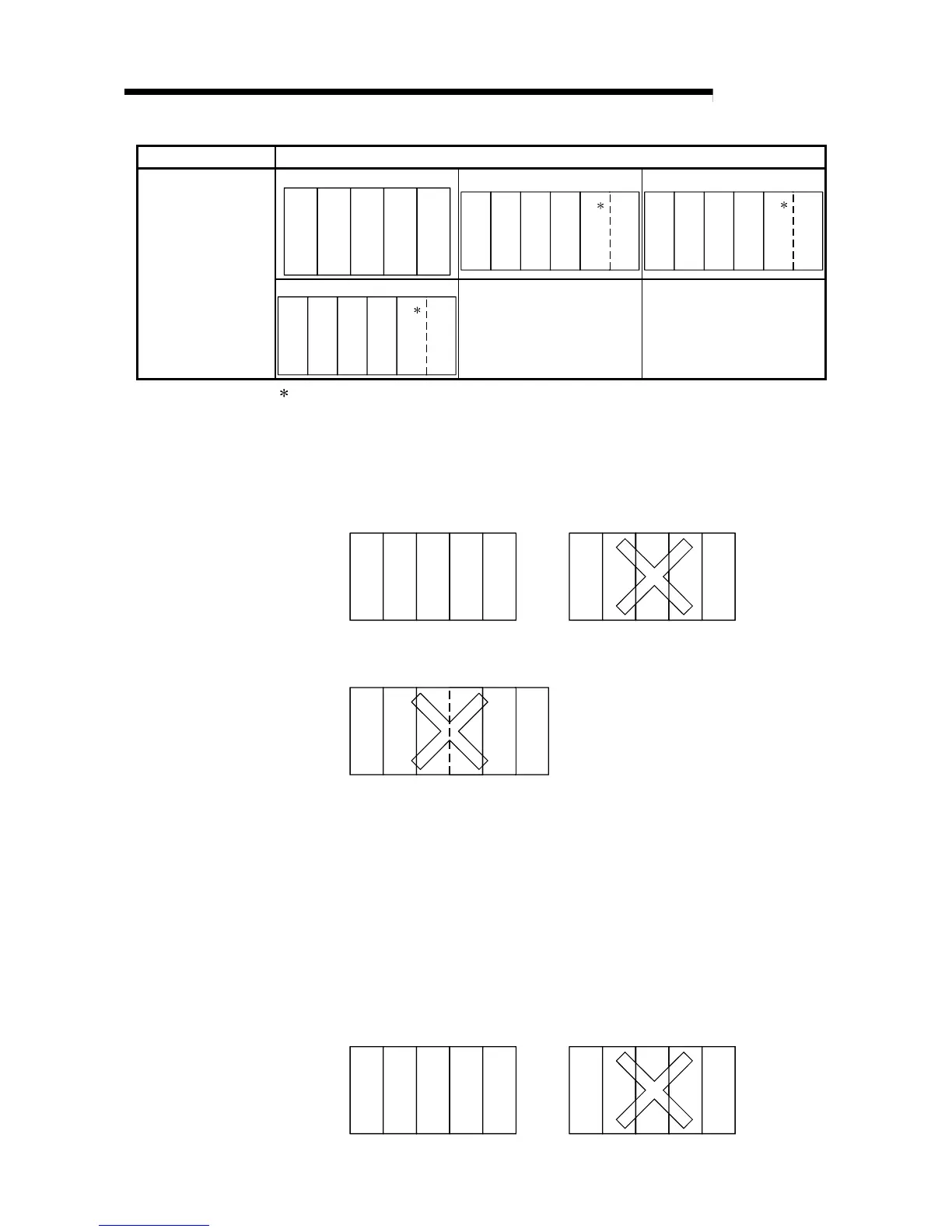
(b) Motion CPUs are mounted together on the slot to the right of the High
Performance model QCPU.
High Performance model QCPUs cannot be mounted to the right of Motion
CPUs.
CPU 0
12
Power supply
Motion CPU
Motion CPU
QCPU
QCPU
Mounting is not allowed
CPU 0
12
Motion CPU
Power supply
Motion CPU
Mounting is allowed
QCPU
QCPU
(c) Mount the PC CPU module at the right end in the multiple PLC system.
No CPU module can be mounted on the right side of the PC CPU module.
CPU 0 1 2
Power supply
QCPU
Motion CPU
3
PC CPU module
(d) An empty slot is secured for future addition of a CPU module.
The number of CPU module including empty slots are set with the No. of
PLC setting, and the type is set in the "CPU (empty)" setting from the slot
immediately to the right of the number of CPU modules set at the "I/O
Assignment" tab screen in the (PLC) "Parameter" dialog box.
For example, when four CPU modules have been set with the multiple PLC
setting and two High Performance model QCPUs and one Motion CPU
have been mounted, the High Performance model QCPUs are mounted in
the CPU module slot and slot 0, the Motion CPU is mounted in slot 1, and
slot 2 is left empty.
However, the empty slot must be on the right side of CPU modules.
CPU 0 1 2
Power supply
Motion CPU
Empty
QCPU
QCPU
CPU 0 1 2
Power supply
Motion CPU
Empty
QCPU
QCPU
Mounting is not allowed
Mounting is allowed
 Loading...


