Operating Instructions MG3 Digital
How to …?
76609409EN-BA-MG3D-V1_6.docx 40/82 2010-08-02
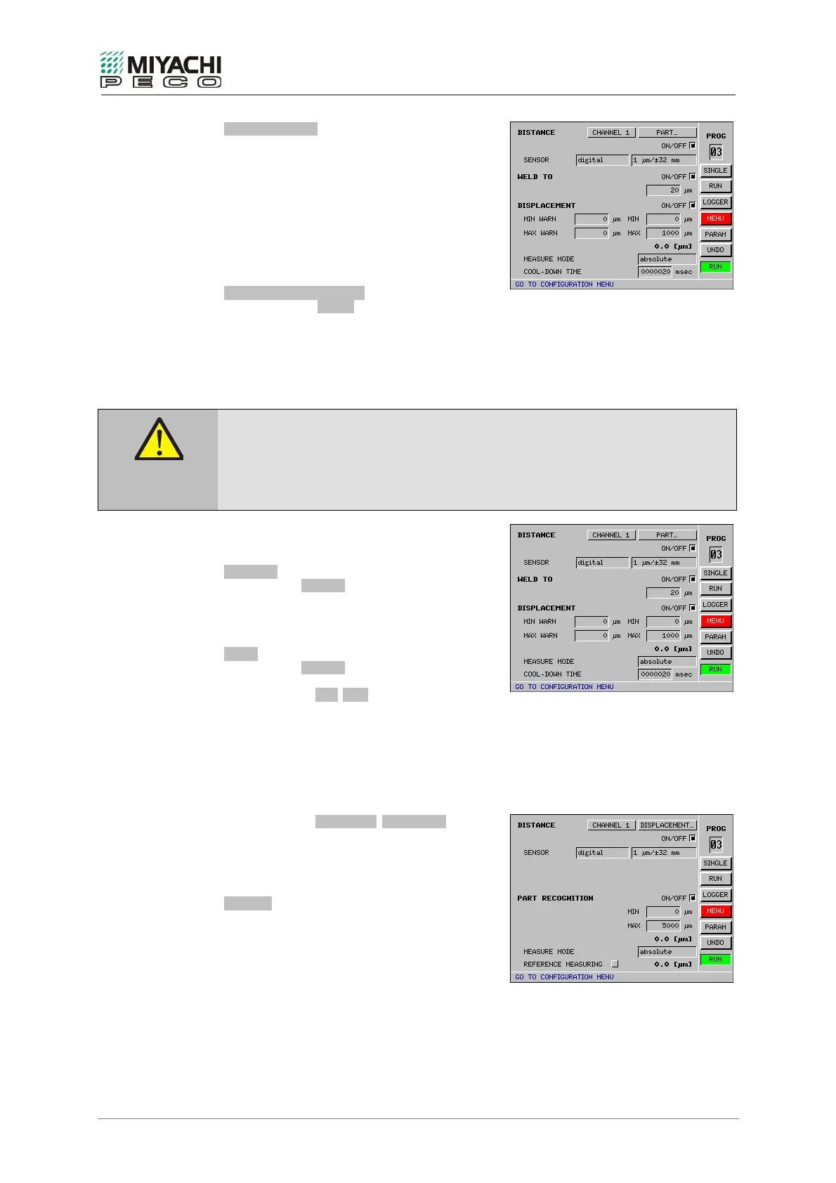
MEASURE MODE
You determine the operating mode through this
input field. You can select between absolute
(standard) and reference.
In operating mode absolute, the distance
(path) is measured that the welding head has
actually covered.
In operating mode reference, the distance
between both electrodes is determined.
Note
This is only for parts detection.
REFERENCE MEASURING
Enabling button START will start reference
measuring.
If reference measuring is concluded, you need
to disable the button again. Now the
determined reference value displays to the
right, beside the button.
To avoid damage to electrodes and welding installation, you need to perform a reference
run:
• prior to first measurement
• after any change on the electrodes
• after any change on the welding head
Caution
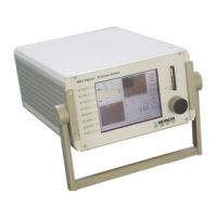
Right above you can toggle between PART… and
FINBAL..
WELD TO
When button ON/OFF is enabled, the welding
current is switched off as soon as the welding
head has reached the displacement preset in
the adjacent input field.
FINAL
When button ON/OFF is enabled, the sinking
path (=displacement) is measured.
The input fields MIN/MAX pre-select the
minimum or maximum sinking depth for
monitoring.
If both values are zero, the monitoring is
deactivated.
The input fields MIN WARN/MAX WARN force
the minimum or maximum warning values for
monitoring.
The monitoring is deactivated with both
values 0.
SENSOR
Here you determine the signal form
(digital/analog) and resolution of the
displacement measuring system connected.
The maximum measurable stroke is specified
additionally in the case of the digital
displacement sensor.
 Loading...