Introduction
Micro-Ion
®
Module Instruction Manual - 356007-GP 11
Installation Operation MaintenanceIntroduction
Filament selection Alternating, automatic, or manual modes
• For a Micro-Ion gauge with yttria-coated iridium filaments, the default is
alternating
Outputs and Indicators
Analog output Logarithmic, 0.50 Vdc/decade, where 1000 Torr = 7 Vdc
Digital RS-485 output
Interface RS-485 two-wire, half-duplex
Communications format ASCII format, eight data bits, no parity, one stop bit
Baud rates 1200, 2400, 4800, 9600, 19200 (default), or 38400 baud
Address 0 to 63, selected by using address switch and RS-485 SA command
LED status indicator Module status indicator lights up to indicate module status.
Pressure display (optional) X.X±Y display format includes two significant digits, a 1-digit exponent, and
a ± sign for the exponent.
Trip point indicators (optional) LED indicator for relay 1 or relay 2 is solid green when corresponding relay
is activated or blinks green when corresponding relay is being configured.
Trip point relays
Relay type Two single-pole, double-throw relays (SPDT)
Relay contacts are silver alloy-gold clad, rated for 1 A at 30 Vdc. The relays
can handle resistive or non-inductive loads.
Relay contact ratings 1 A at 30 Vdc resistive or non-inductive
Minimum hysteresis 5%
Range 1.0 x 10
–9
to 100 Torr
1.0 x 10
–9
to 133 mbar
1.0 x 10
–7
to 1.33 x 10
4
pascal
Default activation pressure Default activation pressures are set to 0.0.
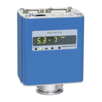
Micro-Ion Plus Module
Micro-Ion gauge sensitivity
At 4 mA emission (high) 18/Torr, 13.5/mbar, .135/pascal
At 0.1 mA emission (low) 20/Torr, 15/mbar, .15/pascal (± 15% variation)
X-ray limit < 3 x 10
–10
Torr, < 3.99 x 10
–10
mbar, < 3.99 x10
–8
pascal
The x-ray limit is the absolute lowest indication from the gauge. It is not

 Loading...