Micro-Ion
®
Module Instruction Manual - 356007-GP 13
Installation Operation MaintenanceBefore You Begin
Chapter 2 Installation
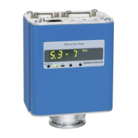
2.1 Module Components The Micro-Ion Plus Module contains a Micro-Ion gauge (Bayard-Alpert type
ionization gauge) and a Conductron heat-loss sensor.
2.2 Installation Procedure The module installation procedure includes the following steps:
1. Install the appropriate pressure relief devices in the vacuum system.
2. Determine the best for the module on the vacuum chamber.
3. Attach the module vacuum chamber fitting to its mate on the vacuum
chamber.
4. Assemble and connect the module wiring.
5. Calibrate the Conductron sensor at atmosphere.
This chapter also explains what to do if radio frequency interference (RFI)
from the module disrupts operation of other electronic devices.
Using the module to measure the pressure of flammable
or explosive gases can cause a fire or explosion resulting
in severe property damage or personal injury.
Do not use the module to measure the pressure of
flammable or explosive gases.
Exposing the module to moisture can cause fire or
electrical shock resulting in severe property damage or
personal injury.
To avoid exposing the module to moisture, install the
module in an indoor environment. Do not install the module
in any outdoor environment.

 Loading...