Installation
Micro-Ion
®
Module Instruction Manual - 356007-GP 19
Installation Operation MaintenanceBefore You Begin
(a) 15K pull-up to 12 Vdc, (LOW) 0 Vdc at 0.80 mA. See Figure 2-4.
(b) Open Collector, no pull-up, 40 Vdc, 50 mA. See Figure 2-4.
(c) Pin must be held LOW for at least 2 msec to activate calibration.
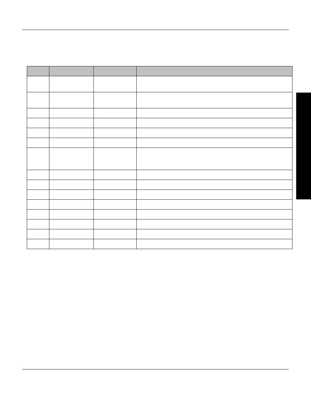
Table 2-2 Connections to 15-pin Subminiature D Connector
Pin # Function Input or Output Description
Pin 1 Micro-Ion gauge
ON/OFF
Input Must be continuously connected to Pin 5 (LOW) to turn gauge ON
(a)
• Removing ground connection turns gauge OFF
Pin 2 Analog output Output • 0.5 Vdc/decade, 7 Vdc maximum
• Ground reference to pin 12
Pin 3 Filament status Output (LOW) Indicates an inoperable filament
(b)
Pin 4 Gauge status Output (LOW) Indicates Micro-Ion gauge is ON (b)
Pin 5 Ground (–) Input Power supply ground
Pin 6 Degas status Output (LOW) Indicates Micro-Ion gauge degas is ON
(b)
Pin 7 Degas ON/OFF Input • Continuous LOW will activate 2-minute degas (a)
• Pressure must be < 5 x 10
–6
Torr (6.66 x 10
–6
mbar,
6.66 x 10
–4
pascal) for degas to start
Pin 8 +24 Vdc power Input +20.4 Vdc to +27.6 Vdc, 26 W nominal
Pin 9 Calibration Input LOW sets atmospheric or vacuum calibration point
(a) (c)
Pin 10 Not used Not used
Pin 11 Keyboard lock Input Continuous LOW locks keyboard (a)
Pin 12 Signal common Output Signal ground (analog output)
Pin 13 RS-485+ Input/output RS-485+
Pin 14 RS-485 – Input/output RS-485 –
Pin 15 Chassis ground Input Chassis ground (cable shield)

 Loading...

