11MCP15-500.7
GROUND
JOINT
UNION
W/ BRASS
SEAT
3"
MIN.
TO
CONTROLS
MANUAL GAS
SHUT-OFF VALVE
GAS
SUPPLY LINE
SEDIMENT
TRAP
PLUGGED 1/8"
NPT TEST GAUGE
CONNECTION
Through hole
in bottom of unit.
(caulk hole to prevent
water leakage.)
Side Gas Connection
Bottom Gas Connection
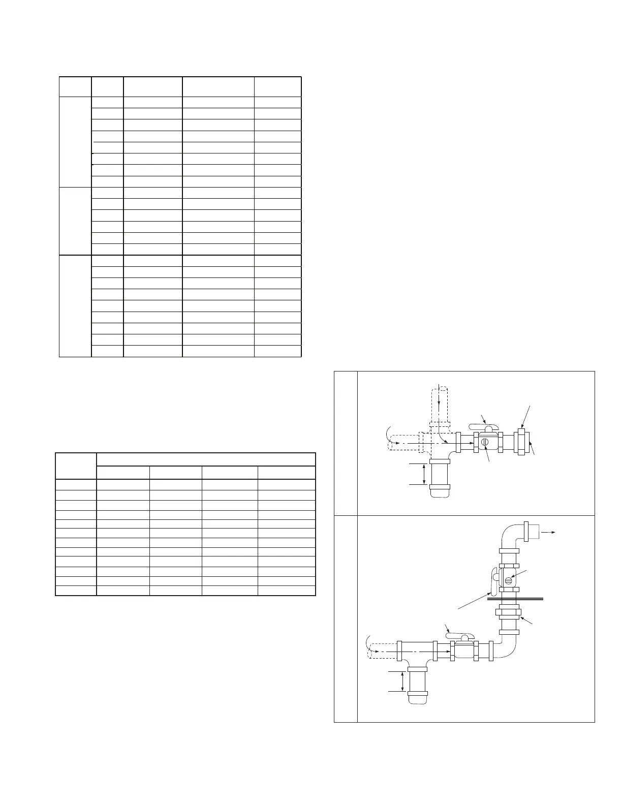
Figure 11.1 - Recommended Sediment Trap/Manual
Shut-off Valve Installation
SUPPLY LINE
GAS
SUPPLY LINE
GROUND JOINT
UNION WITH
BRASS SEAT
MANUAL GAS
SHUT-OFF VALVE
3"
MIN.
SEDIMENT
TRAP
PLUGGED
1/8" NPT TEST
GAUGE CONNECTION
TO GAS
CONTROLS
j Valve is in the “OFF” position when handle is perpendicular to pipe.
j
GAS CONNECTIONS
3. The gas piping to the unit can enter the unit from the side
of the unit (refer to the unit dimensions) or from below (refer
to the base dimensions). A drill locator sticker and dimple is
located on the side of the unit to indicate the safe area for
drilling the hole for side gas pipe entry on B- and C-Cabinet
sized units. D-Cabinet sized units include a holes with
grommets for side pipe entry. Install a ground joint union
with brass seat and a manual shut-off valve external of the
unit casing, and adjacent to the unit for emergency shut-off
and easy servicing of controls, including a 1/8" NPT plugged
tapping accessible for test gauge connection (see Figure
11.1). Verify the manual shut-off valve is gas tight on an
annual basis.
NOTE: For bottom piped units, some local codes may require
a manual shutoff valve external to the unit casing. In this case,
the gas piping must exit the unit through the side, followed by
the manual shut-off valve, piped back into the unit side, and
lead to an additional union and manual shut-off valve.
4. Provide a sediment trap before each unit in the line where
low spots cannot be avoided (see Figure 11.1).
5. When Pressure/Leak testing pressures above 14" W.C.
(1/2 psi), close the field installed shut-off valve, disconnect
the appliance and its combination gas control from the gas
supply line, and plug the supply line before testing. When
testing pressures 14" W.C. (1/2 psi) or below, close the
manual shut-off valve on the appliance before testing.
Table 11.1 - Natural Gas Heating Gas Consumption
j Natural gas consumption based on a heating value of 1050 Btu/cu. ft.
k C-Cabinet units consist of two furnaces that together total the value shown in
Table 11.1.
l D-Cabinet units consist of two furnaces that together total the value shown
in Table 11.1 for sizes up to 800,000 Btu/hr. For sizes over 800,000 Btu/hr,
the unit consists of four furnaces that together total the value shown in Table
11.1.
Digit 6 Digit 18
F 150,000 143 1/2"
G 200,000 190 3/4"
H 250,000 238 3/4"
J 300,000 286 3/4"
K 400,000 381 3/4"
R 175,000 167 1/2"
S 225,000 214 3/4"
T 310,000 295 3/4"
J 300,000 286 3/4"
K 400,000 381 1"
L 500,000 476 1"
L 600,000 571 1"
U 350,000 333 1"
V 450,000 429 1"
K 400,000 381 1.5" x 2
L 500,000 476 1.5" x 2
M 600,000 571 1.5" x 2
Q 800,000 762 1.5" x 2
1 900,000 857 1.5" x 2
2 1,000,000 952 1.5" x 2
3 1,200,000 1143 1.5" x 2
4 1,400,000 1333 1.5" x 2
5 1,600,000 1524 1.5" x 2
C
B
D
m Gas pipe capacities based on gas pressure up to 14" W.C. through Schedule
40 pipe with a pressure drop of 0.3" W.C. for Natural gas with a specific
gravity of 0.60.
Pipe
Length
(feet)
Gas Pipe Diameter
1" 1-1/4" 1-1/2" 2"
10 520 1050 1600 3050
20 350 730 1100 2100
30 285 590 890 1650
40 245 500 760 1450
50 215 440 670 1270
60 195 400 610 1150
70 180 370 560 1050
80 170 350 530 990
90 160 320 490 930
100 150 305 460 870
125 130 275 410 780
150 120 250 380 710
Table 11.2 - Gas Pipe Capacities (Cu. Ft. per Hour) m