14 MCP15-500.7
Condensate Drain and Trap Installation
(Condensing Furnace Type Only)
For Condensing furnace types, as determined from Table 12.1
on page 12, during heating operation, condensate is produced
in the furnace sections. The installation requires condensate
drain systems from each furnace section, as shown in Figures
14.1 and 14.2 and described below. Condensate trap kits are
provided with the unit.
1. For proper heating system performance, the condensate
drain system must include a trap for each furnace.
B-Cabinet units have one furnace while C-Cabinet units
have two furnaces.
2. All joints must be watertight to prevent leakage of
condensate. The drains must be extended down through
the base of the unit and into the heated space below.
3. Each heat exchanger drain assembly includes a threaded
elbow that is oriented down. Once the male threaded PVC
adapters, included with the kit, are glued to the PVC drain
pipe (by others) that extends into the space, they are to be
routed up through the holes in the unit base pan and
screwed into the elbow connections. The threads must be
sealed to prevent leaks.
4. Unions are recommended to permit maintenance of the
drains and to facilitate service of the heater. A union is
shown on both sides of each trap.
5. A vacuum breaker is required after each trap. The vacuum
breaker should be constructed so that dirt and debris do
not enter and clog the drain system.
6. Local code permitting, the condensate drain systems may
be joined after the traps and connected to a sanitary drain
within the building. Because the condensate produced is
acidic, some municipalities may require that the
condensate be neutralized before being discharged into the
sanitary sewer. A condensate neutralizer tube kit is
available from Modine to reduce the pH of the condensate.
A single tube can be used for drains that are joined after
the traps providing the tube is installed after the junction.
Refer to the instructions that come with the kit.
7. For proper operation, the traps must be primed with water.
The traps must be installed with the higher side connected
to the heater and the lower side connected to the drain.
8. If there is an opportunity that the temperature in the space
will fall below freezing during non-operating periods, the
condensate drain systems and secondary heat exchanger
must be completely drained to prevent freeze damage.
Alternately, heat tape can be applied to the drain pipe
system in accordance with the heat tape manufacturers
instructions.
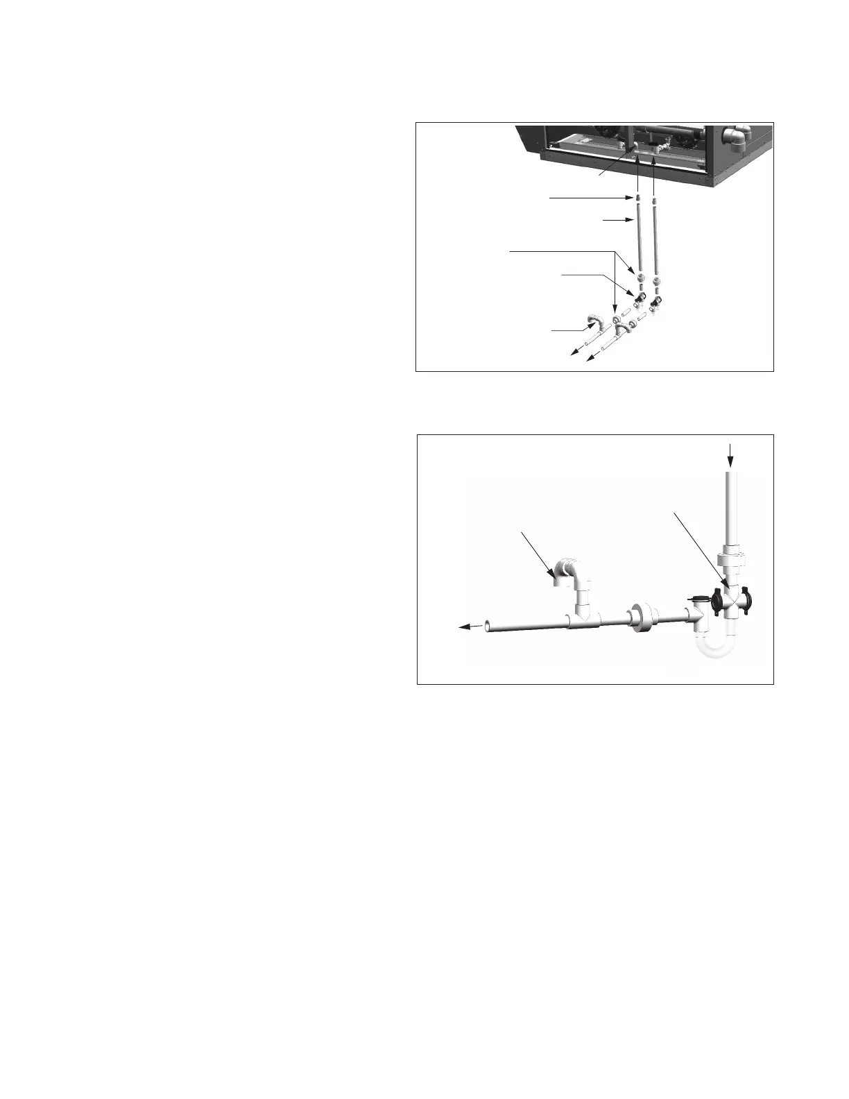
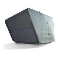
Figure 14.2 - Drain System Trap/Vacuum Breaker
Figure 14.1 - Furnace Condensate Drain/Trap
System j
3/4" Threaded Elbow on Heat Exchanger Drain
Assembly (included with kit)
3/4" Male Threaded PVC Adapter
(included with kit)
3/4" PVC Pipe (by others) with Sufficient Length
to Reach the Heat Exchanger Drain Assembly
from the Inside of the Building
3/4" Unions (by others)
Recommended for Ease of Future Service
PVC "EZ-Trap" (included with kit) for
Proper Drain Trapping (a 3/4" to 1" bushing
by others may be required)
Note: The trap must be located in a heated
space or protected to avoid freezing.
Vacuum Breaker and Drain Piping
Components (by others)
To Building
Drain System
j C-Cabinet sized unit shown with two condensate drain systems. B-Cabinet
sized units require only one drain system.
Note: Drain pipe from unit
must enter the high side of
the drain trap.
Note: Refer to figure above for determination of parts supplied by others.
Vacuum Breaker
Exchanger Drain
Assembly on Unit
To Building
Drain System
GAS HEATING OPTION CONDENSATE DRAIN AND TRAP INSTALLATION