13MCP15-500.7
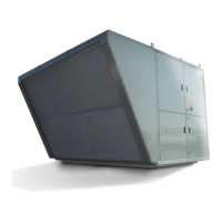
Figure 13.4 - Orientation of Installed Vent Terminal
for Condensing Gas Furnace Option (C-Cabinet)
DISCHARGE ELBOWS ORIENTED
TO EXHAUST STRAIGHT DOWN
(refer to
Instructions
Step 1)
(refer to Instructions Step 3)(refer to Instructions Step 2)
Figure 13.3 - Power Exhauster Vent Terminal for
Condensing Gas Furnace Option
For C-Cabinet units with Condensing furnace types, as
determined from Table 12.1 on page 12, refer to Figures 13.3
and 13.4 for vent termination installation details. The
installation steps are as follows:
Step 1: Insert small diameter outside vent pipe termination
through enclosure wall grommet and into the flexible
rubber coupling on the right side power exhaust
outlet. Tighten the clamp on the flexible coupling to
secure the vent pipe.
Step 2: Insert large diameter inner vent pipe assembly into
the flexible rubber coupling on the left side power
exhaust outlet. Tighten the clamp on the flexible
coupling to secure the vent pipe.
Step 3: Insert large diameter outside vent pipe termination
through enclosure wall grommet and into the
interlocking joint of the inner vent pipe assembly from
Step 2.
Step 4: Verify that the bird screens are inserted in the outlet
elbow.
Once complete, proceed to the “Condensate Drain and Trap
Installation” section.
Discharge Elbows must
be oriented to exhaust
straight down.
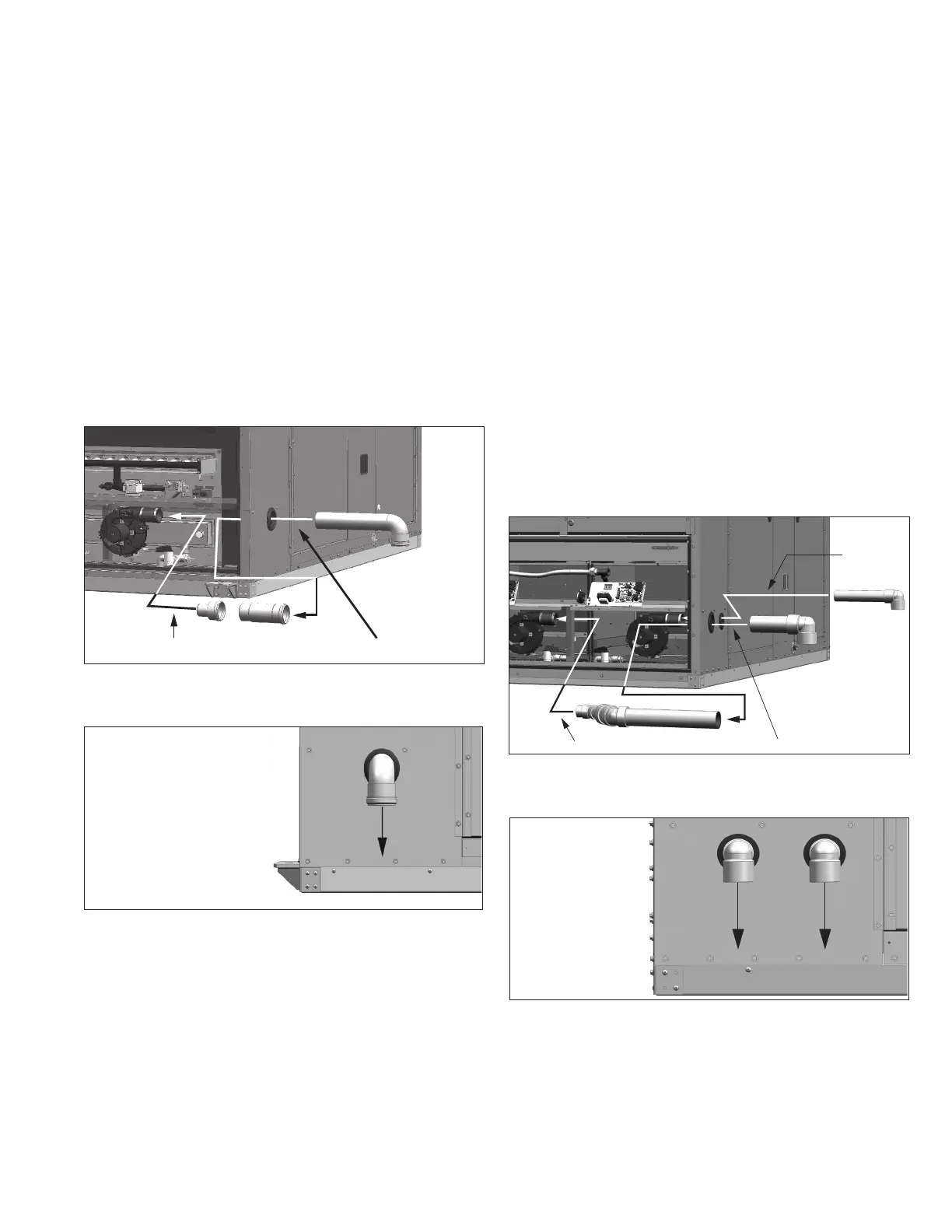
Figure 13.1 - Power Exhauster Vent Terminal for
Condensing Gas Furnace Option
(refer to Instructions Step 1) (refer to Instructions Step 2)
Figure 13.2 - Orientation of Installed Vent Terminal
for Condensing Gas Furnace Option (B-Cabinet)
Discharge Elbow must be
oriented to exhaust
straight down.
Condensing Furnaces (B-Cabinet)
For B-Cabinet units with Condensing furnace types, as
determined from Table 12.1 on page 12, refer to Figures 13.1
and 13.2 for vent termination installation details. The
installation steps are as follows:
Step 1: Insert short vent pipe length into the vent pipe
reducer. Insert that assembly into the rubber coupling
on the power exhauster outlet. Tighten the clamp on
the flexible coupling to secure the vent pipe.
Step 2: Insert the outer vent pipe with termination elbow
through the enclosure wall grommet and into the vent
pipe section installed in Step 1.
Once complete, proceed to the “Condensate Drain and Trap
Installation” section.
Condensing Furnaces (C-Cabinet)
GAS HEATING OPTION VENT TERMINALS AND COMBUSTION AIR HOODS