19MCP15-500.7
START-UP PROCEDURE - CONTINUED
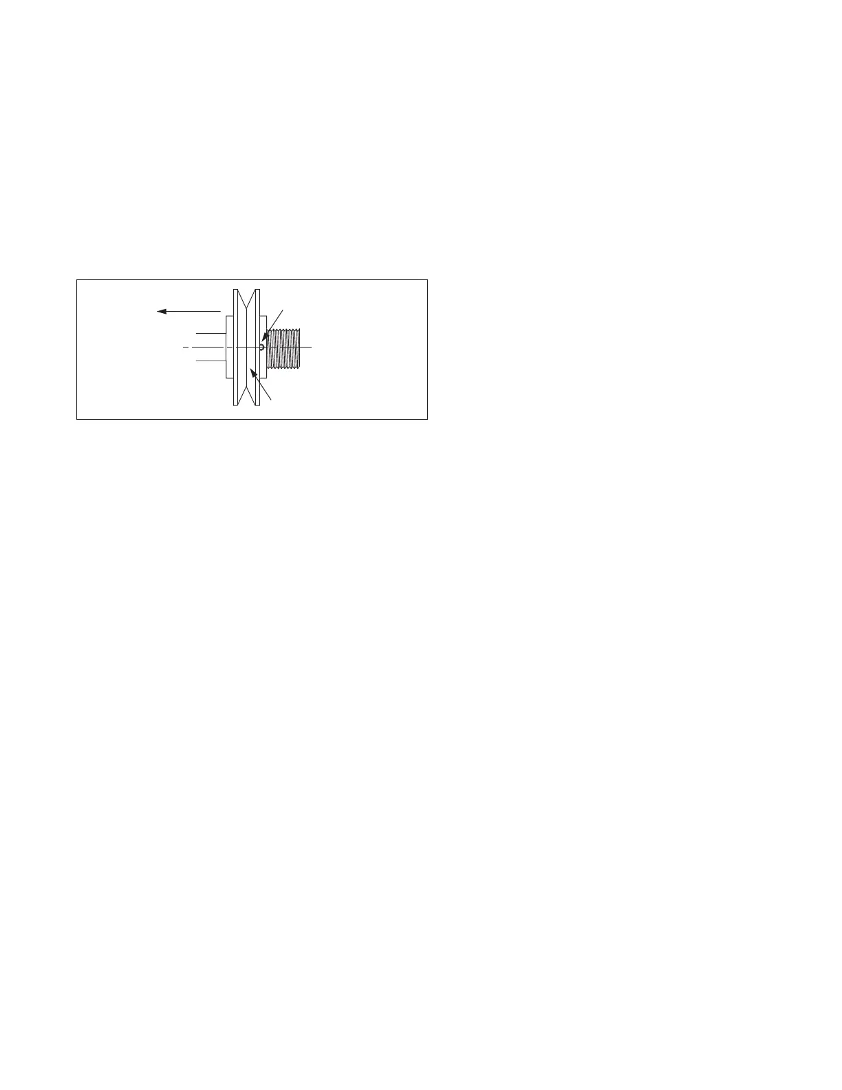
Toward Motor
Set Screw
Adjustable Half
of Sheave
Figure 19.1 - Motor Sheave Adjustment
Blower Adjustments – Belt Drive Fans
All belt drive supply fan and, if applicable, exhaust fan speed
adjustments can be made with the adjustable sheave on the
blower motor as follows:
1. Turn off power to the unit at the disconnect switch. If
equipped with gas heat option, turn all hand gas valves to
the “OFF” position.
2. Loosen the belt tension and remove the belt.
3. On the motor sheave, loosen the set screw on the side
away from the motor (see Figure 19.1).
4. To increase the blower speed, turn the adjustable half of
the sheave inward. To decrease the blower speed, turn the
adjustable half of the sheave outward. The sheave half is
adjustablein½turn(180°)increments.Each½turn
represents approximately a 2-5% change in blower speed
and airflow volume.
5. Tighten the set screw on the flat portion of the sheave shaft.
6. Replace the belt and verify that the belts are aligned in the
sheave grooves properly and are not angled from sheave
to sheave.
7. Turn on power to the unit and initiate blower motor
operation. For guidance, refer to the Controls Manual.
8. Check the motor amps to ensure the maximum motor amp
rating is not exceeded. Verify airflow volume and repeat
steps above for further adjustment.
9. If equipped with gas heat, turn on the gas and initiate burner
operation. For guidance, refer to the Controls Manual.
10. Verify the temperature rise and supply air temperature of
the heating section do not fall outside the range or exceed
the maximums shown in Table 18.1. Airflow can be
approximated with the following formula:
CFM = (Input Btu/hr x Eff) / (1.08 x Temp Rise)
where Eff (Efficiency) is determined from Table 18.1
11. After 24 hours of operation, retighten the setscrews to the
torque listed in the owners manual on the bearing, sheave,
and blower wheel to avoid damage to the unit.
Air Flow Proving Switch / Optional Dirty Filter Switch
The air flow proving switch is factory installed in the blower
compartment. The purpose of the air flow proving switch is to
cut power to the controls if a positive pressure is not measured
by the switch. This could be caused by a lack of air movement
through the evaporator coil or heat exchanger.
The optional dirty filter pressure switch is factory installed in
the filter section. The dirty filter pressure switch monitors the
pressure differential between the two sides of the filters. When
the filters become dirty, the differential pressure increases and
trips the pressure switch which initiates an alarm from the Carel
controller. The pressure differential switch must be field set
because setting the switch requires the blower to be inoperation
and the ductwork to be installed.
Setting the Air Flow Proving or Dirty Filter Switch
1. Ensure that the unit filters are clean. Replace if necessary.
2. Using the Modine Control System controller interface, start
blower operation.
3. Turn the set screw of the pressure switch clockwise until it
stops.
4. With the wires removed from the common and normally
open terminals of the switch, measure continuity and turn
the adjustment screw counter-clockwise until the switch
makes. Then turn the adjustment screw one additional turn
counter-clockwise to account for dirty filters or other system
static changes.
Variable Air Movement Applications
Units may be supplied with variable frequency drives for
applications where variable air volume is required. The
minimum air flow may be varied between 50 and 100% of the
full speed air flow depending on the controls selection of the
unit, but never less than the following:
• B-Cabinet units: 1100 CFM
• C-Cabinet units: 3000 CFM
• D-Cabinet units: 4000 CFM
• All units with Gas Heat: Minimum airflow as listed on the
Gas Heat Serial Plate
Refer to the Controls Manual for additional information.