18 MCP15-500.7
START-UP PROCEDURE - CONTINUED
Blower Adjustments – Direct Drive Fans
All direct drive supply fan speed adjustments can be performed
with the Modine Control System programmable microprocessor
controller. There are two ways to access the menus:
1. Using the user interface on the main unit controller.
2. Using the pGD1 Digital Display/Interface Module.
For guidance on either method above, refer to the latest
revision of the following documents for additional warnings,
cautions, controller location, instructions, and menu navigation:
• ControlsManual,MCP15-525.
• pGD1DigitalDisplay/InterfaceModuleInstallation
Instructions, MCP15-543.
The blower adjustments are made as follows:
1. Ensure unit is running at the maximum airflow setting for
the control type selected. For example, if the unit has
Multi-Speed or Variable Speed fan control, ensure the unit
is operating at the highest speed setting.
2. On the keypad navigate to menu “G. Service -> f.
SERVICE SETTINGS”. At this menu, you will be prompted
to enter the Service password of 1500.
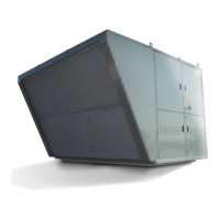
3. Navigate to “c. Control Settings” and scroll to the “Supply
Fan Control (CS6)” screen. See Figure 18.3.
4. Adjust the Air Balance Adj parameter up or down to obtain
the design airflow given the actual static pressure.
5. In the event you are unable to increase or decrease the
motor speed to the desired air balance please consult your
factory representative.
6. Check the motor amps to ensure the maximum motor amp
rating is not exceeded. For units equipped with a VFD,
measure the amps at the incoming lines to the motor. If
the unit has dual supply fans, measure each motor
individually. Verify airflow volume and repeat steps above
for further adjustment.
7. If equipped with gas heat, turn on the gas and initiate
burner operation. For guidance, refer to the Controls
Manual.
8. Verify the temperature rise and supply air temperature of
the heating section do not fall outside the range or exceed
the maximums shown in Table 18.1. Airflow can be
approximated with the following formula:
CFM = (Input Btu/hr x Eff) / (1.08 x Temp Rise)
where Eff (Efficiency) is determined from Table 18.1
Figure 18.3 - Control Settings Screen CS6
Table 18.1 - Allowable Temperature Rise Range and
Maximum Supply Air Temperature
Casing
Size
Heat
Type Rating
Eff
(for formula)
Temp Rise
Allowable
Temp Rise
Range
Max Supply
Air TempDigit 6 Digit 17 Digit 18 Digit 19
B
1 A, B, C, D 1.00 N 1 - 100°F 100°F
2 or 3
F, G, H, J, K 0.81
L 30 - <70°F
130°F
H 70 - 100°F
R, S, T 0.94 N 30 - 100°F 100°F
C
1 A, B, C, D, E 1.00 N 1 - 100°F 100°F
2 or 3
J 0.81 N 30 - 75°F
130°F
K, L, M 0.81
L 30 - <70°F
H 70 - 100°F
U, V 0.81
L 30 - <70°F
100°F
H 70 - 100°F
D
1 A, B, C, D, E 1.00 N 1 - 100°F 100°F
2 or 3
K 0.81 L 30 - 75°F
130°F
L, M, Q 0.81
L 30 - <70°F
H 70 - 100°F
1, 4
0.81
H 70 - 120°F
2, 3, 5 H 60 - 120°F
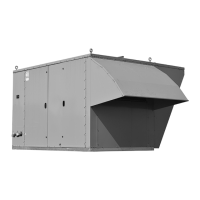
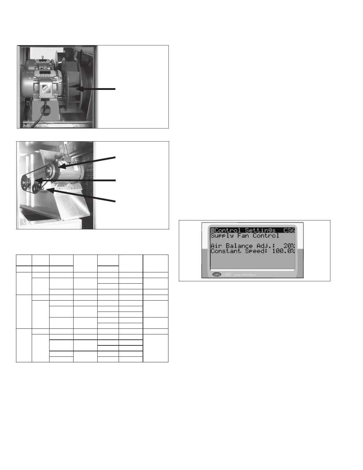
Figure 18.2 - Belt Drive Blower Example
Figure 18.1 - Direct Drive Blower Example
Direct Driven Blower
(dual blower shown)
Motor Sheave
(adjustable)
Blower Sheave
(non-adjustable)
Automatic Belt
Tensioner