15MCP15-500.7
HOT WATER PIPING CONNECTIONS
CAUtIoN
1. Units not approved for use in potable water systems.
2. Do not operate the unit with steam. The coil is not designed
for steam condensate removal which can damage the unit.
3. Hot water supplied to the hot water heating option must
not exceed 180°F temperature or 75 PSIG pressure.
Figure 15.2 - Typical 2-Way Piping Installation
(piping and components by others)
2-WAY CONTROL
VALVE
SHUT-OFF
VALVE
SHUT-OFF
AIR VENT
RETURN
SUPPLY
SETTER
CIRCUIT
VALVE
UNION
UNION
STRAINER
UNION
HOT WATER
COIL
HOSE BIB DRAIN
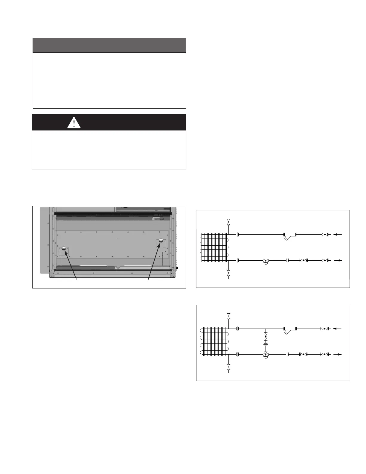
1. Models with a factory installed hot water heating coil (for use
with water or propylene glycol fluids) are supplied with 1-1/2"
sweat connections (1.625").
2. The entering water temperature (EWT) supplied to the
heating coil must not exceed 180°F.
3. The fluid flow rate must not exceed 50 gallons/minute (GPM)
and fluid pressure must not exceed 75 psi.
4. It is recommended to use an inhibited glycol solution that is
designed for HVAC applications for corrosion protection and
freeeze protection for the lowest possible outside air
temperatures for the installed location. Failure to protect
against freezing can result in damage to the coil and
property.
5. Provide adequate pipe hangers, supports, or anchors to
secure the piping system independently of the coil to prevent
excess vibration and stress that can damage the piping and
joints.
6. All field brazing and welding should be performed using high
quality materials and an inert gas purge (such as nitrogen) to
reduce oxidation of the internal surface of the coil.
7. System piping should be flexible enough to allow for thermal
expansion and contraction of the coil and piping components.
8. Refer to Figures 15.2 and 15.3 for typical piping system
design and the following recommended items:
•Installshut-offvalvesinlinestoandfromtheunittoallow
for maintenance or replacement of the coil without shutting
down and draining the entire system.
•Installunionsforeaseofpipingcomponent/coilremoval.
•Includeacircuitsetterinthereturnlinetoregulateflow.
Figure 15.1 - Hot Water Coil Connections
Supply Connection Return Connection
Optional Factory Installed Freeze Stat
When equipped with the optional Coil Freeze Stat, an auto-
resetting capillary type freeze stat (see Figure 50.1) is factory
installed immediately below and across the face of the hot
water coil. The stat is set to trip at 40°F (adjustable) and will
automatically reset when the coil temperature rises 5°F above
the setpoint. If the stat has tripped, the unit controls would
respond by closing the outdoor air damper, opening the return
air damper (if applicable), de-energize the supply air fan, open
the hot water coil valve 100%, and log the alarm on the
controller. The freeze stat can be removed from the unit for
servicing as discussed in the Maintenance section.
Figure 15.3 - Typical 3-Way Piping Installation
(piping and components by others)
3-WAY CONTROL
VALVE
SHUT-OFF
VALVE
SHUT-OFF
AIR VENT
RETURN
SUPPLY
SETTER
CIRCUIT
VALVE
BALANCING
VALVE
UNION
UNION
STRAINER
UNION
HOT WATER
COIL
UNION
HOSE BIB DRAIN
THIS SECTION APPLIES TO UNITS WITH
OPTIONAL HOT WATER HEAT
(MODEL DIGIT 17=4).
IF THE UNIT DOES NOT HAVE HOT WATER
HEAT, SKIP TO PAGE 16.
REVIEW BEFORE PROCEEDING
•On3-wayvalvecontrolconfigurations,includeabalancing
valve between the supply line and control valve to balance
the system.
•Includeahosebibdrainvalveonthebottomofthesupply
manifold to allow for periodic flushing of the system to
remove sediments from the coil.
•Includeapipelinestraineronthesupplylinetoprevent
sediment from reaching the coil.
•Includeanairventatthetopofthereturnmanifoldtobleed
off accumulated air in the system. Air in the system will
generate noise and may cause water hammer that can
damage the joints of the piping and coil.
•Includeeithera2-wayor3-waymodulatingcontrolvalve
designed for a 0-10VDC control signal. The valves will be
automatically modulated by the unit’s Carel controller to
maintain the supply air temperature setpoint. Note that the
control valve must be a normally open, spring return type
valve. This is to allow hot water to flow through the coil for
freeze protection when the unit is shut down. Refer to the
Freeze Stat Option section for additional detail.
•Hotwaterpipesshouldbeinsulatedtoreduceheatlossand
to prevent overheating of the end compartment.
9. Leak test the coil and connections as outlined in the
Start-Up section.