8 MCP15-500.7
CONDENSATE DRAIN INSTALLATION
All units require a drain system with a condensate trap to be
connected to the condensate drain pan connection which is
accessible from the exterior of the unit casing. Failure to install
a condensate drain trap may result in condensate overflowing
from the drain pan, causing damage to the unit and building.
See Figure 30.1 or 31.1 for location. The drain system is to be
installed as follows:
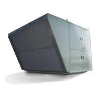
1. The condensate drain pan includes a 1-1/4" female NPT
stainless steel connection accessible from the exterior of the
unit casing. Do not reduce the drain diameter. A drain pan
connection kit is shipped loose for field installation to allow
connection exterior to the casing. Refer to Figure 8.1 for
assembly details.
TRAP HEIGHT
(6" MINIMUM)
1/2 x TRAP
CAPPED
CLEANOUT
HEIGHT
Figure 8.1 - Condensate Drain Pan Connection Kit
Threaded Connection on
Evap Coil Drain Pan
Note: All kit components shown
are factory supplied for field installation.
Threaded Nipple
Corrosion Resistant
Steel Washer
Corrosion Resistant
Steel Locknut
Rubber Washer
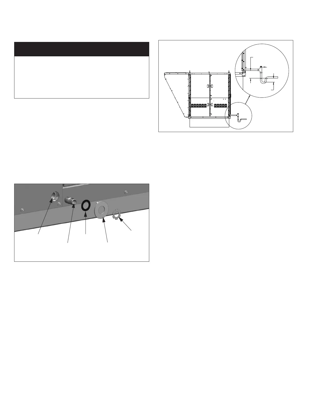
Figure 8.2 - Condensate Drain Trap Installation
Note: All piping components
shown are supplied by others.
2. The drain line should include provisions for disconnecting the
line at or near the unit for maintenance/servicing of the unit.
The drain line must not interfere with access panels, which
are removable for maintenance/service.
3. The drain line must include a trap immediately after the
unit, as shown in Figure 8.2. Failure to do so will result
in condensate that cannot properly drain from the unit,
eventually causing the drain pan to fill and overflow. If the
drain pan overflows, significant damage can occur to the unit
and/or building on which the unit is installed. A drain pan float
switch is included as standard and will disable the unit if the
maximum condensate level is reached.
4. The design of the trap is critical to ensure proper drainage.
If the trap is not constructed properly with the dimensions
as outlined in the following instructions, air could be drawn
through the drain pipe and into the system or could back up
into the drain pan.
•Thedrainislocatedonthesuctionsideofthemain
supply air fan, resulting in a negative pressure relative to
outside the unit cabinet. The trap height must be at least
6” to account for maximum negative pressure, including
allowance for dirty filters. Note that the trap height is the
difference in height from the drain connection of the unit to
the leaving side of the trap. Refer to Figure 8.2.
•Thetrapdepthmustbe½xthetrapheight.Forexample,if
the trap height is the minimum 6”, the trap depth must be 3”
(see Figure 8.2).
•Formaintenance,itisrecommendedtohaveacapped
cleanout at the top of the trap as shown in Figure 8.2.
5. After the exit from the trap, the drain must be pitched
down from the unit connection at least 1” for every 10 feet
of horizontal run to promote proper drainage. If the local
installation code allows, the drain can be run to a waste
water system.
6. If the trap may experience below freezing temperatures
during non-cooling periods, heating wraps must be used to
avoid water from freezing in and damaging the trap and drain
system.
7. The trap must be primed before the unit is put into operation
and properly maintained on a regular schedule. Refer to the
Start-Up Procedure section and the Maintenance section for
additional guidance.
IMPoRtANt
A properly designed drain with trap must be installed
immediately after the unit evaporator coil condensate drain
pan connection. Failure to do so will result in condensate
that cannot properly drain from the unit, eventually causing
the drain pan to fill. To prevent damage to the building or
unit, a drain pan float switch is included as standard and will
disable the unit if the maximum condensate level is reached.
Evap Condensate Drain Trap Installation