7MCP15-500.7
DUCT INSTALLATION AND UTILITY CONNECTIONS
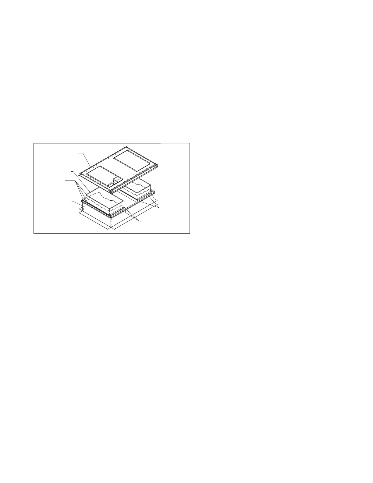
Figure 7.1 - Discharge and/or Return Air Connectors
5. To assure proper air flow from the unit, follow these duct
design recommendations:
a. Be sure ducts are properly sized and installed.
b. As a general rule, all discharge ducts should have a
straight run of at least three (3) hydraulic duct diameters
before making turns in the ductwork.
Hydraulic Duct Diameter for Rectangular Ducts = 4A/P
Hydraulic Duct Diameter for Circular Ducts = D
where:
A = Cross Sectional Area of Rectangular Duct
P = Perimeter of Rectangular Duct
D = Diameter of Round Cut
c. Wherever turns in the duct work are made, include
turning vanes.
d. Supply air ducts in a “T” configuration should be
avoided to prevent air temperature stratification. If this
configuration must be used, provide appropriate mixing
devices and/or the necessary straight duct length before
the “T” to provide uniformly mixed air temperature
delivery to both supply air duct trunks.
Utility Connections
Utility and control connections can be made to the unit from
the bottom or through the fixed side panels. Holes can be field
drilled in fixed side panels to accommodate utility connections
as shown on the unit dimensional drawings and the utility
entrance location area label located on the unit. All gas and
electrical connections to the unit must be weatherized so they
are watertight.
RETURN AIR
CONNECTOR
DISCHARGE AIR
CONNECTOR
90° FLANGED
DUCTWORK
(By Installer)
UNIT BASE
(Shown without
unit for clarity)
ROOF
CURB
BEFORE UNIT
INSTALLATION
CAULK ALL MATING
SURFACES ➀
(Caulk by installer)
➀ If roof curb is supplied
by Modine, full perimeter
gasket material is supplied
and caulking is not necessary.
Duct Installation
1. The unit is designed to accept 90° flanged ductwork on both
the supply and return air openings. Refer to the roof curb or
the unit base dimensional drawings to determine the location
of the openings.
2. Acoustic duct liners are recommended on all internal supply
and return air ducts.
3. When ductwork is installed prior to unit arrival, flexible
connections should be included to make connections easier
and to simplify possible future service.
4. When a roof curb is used in conjunction with factory supplied
discharge and/or return air connectors, the ductwork can be
fastened to the connectors prior to the unit installation. The
connectors will accept 90° flanged ductwork (see Figure 7.1).