28 MCP15-500.7
START-UP PROCEDURE - CONTINUED
THE FOLLOWING SECTION APPLIES ONLY TO B-CABINET SIZED
UNITS WITH OPTIONAL ENERGY RECOVERY EXHAUST OPTION
(MODEL NOMENCLATURE DIGIT 6=B AND DIGIT 21=A, B, OR C).
IF THE UNIT DOES NOT HAVE THIS OPTION, SKIP TO PAGE 30.j
REVIEW
BEFORE
PROCEEDING
1. Turn off power to the unit at the disconnect switch. If
equipped with gas heating option, turn all hand gas valves
to the “OFF” position.
Note: The dead front disconnect switch, if included, is
factory installed in the controls/compressor compartment
section (refer to the figures on pages 32 through 35). The
disconnect switch is designed so that it must be turned
“OFF” before entry to the compartment can be obtained.
When in the “OFF” position, power is disconnected to all
unit wiring electrically following the switch (see
WARNING).
2. For units equipped for dual power supply sources, both
sources of power must be disconnected to prevent
electrical shock and equipment damage.
3. Open the power compartment, controls compartment, and
blower access doors. Refer to Figure 29.1 for location of
doors and internal components.
4. Check that the supply voltage matches the unit supply
voltage listed on the Unit Serial Plate. Verify that all
wiring is secure and properly protected. Trace circuits to
insure that the unit has been wired according to the wiring
diagram.
5. Check that fuses or circuit breakers are in place and sized
correctly.
6. Check to see that there are no obstructions to the intake
and discharge of the unit.
IMPoRtANt
1. On units with the electric preheat option, to prevent
premature heat exchanger failure, check to be sure the
blower has been set to deliver the proper airflow for the
application. Refer to page 17 for Blower Adjustments.
2. The exhaust fan is not designed for high temperature
or smoke control exhaust applications. Exhaust air
temperature must not exceed 104°F. Operating the
exhaust fan above 104°F will result in failure of the
exhaust fan.
WARNING
WARNING
1. The power supply wiring for the Energy Recovery
Section comes from a single point power connection
on the unit. Disconnect power supply at model MPR
before making wiring connections to prevent electrical
shock and equipment damage.
2. For units equipped for dual power supply sources, both
sources of power must be disconnected to prevent
electrical shock and equipment damage.
j If the unit is a C-cabinet size and has energy recovery exhaust, refer to the latest revision of literature #MCP15-520 for the
Start-Up Procedure for the Model ERM Energy Recovery Module.
7. Check the belt tension and sheave alignment for the
exhaust blower.
8. Most motors are permanently lubricated for long life and
are identified as such on the motor nameplate. Most blower
bearings are permanently lubricated as well, except for
pillow block bearings or those identified with grease fittings.
For motors or blower bearings that are not permanently
lubricated, lubricate according to the manufacturer’s
instructions.
9. Check to make sure that all filters are in place and that
they are installed properly according to direction of air flow.
10. Perform a visual inspection of the unit to make sure no
damage has occurred during installation.
11. Turn on power to the unit at the disconnect switch.
Note: The unit includes a blower door switch that is factory
installed inside the blower section door on the access side
of the unit. When the blower section door is opened, the
switch is opened and interrupts power to the low voltage
circuit and de-energizes the motor starter that controls
blower motor operation.
12. Check the Modine Control System controller and exhaust
fan blower motor for electrical operation. If this does not
function, recheck the wiring diagram. Check to insure that
none of the Control Options have tripped.
13. Check to make sure that the economizer wheel bypass
damper (if equipped) opens properly without binding.
14. Check the blower wheel for proper direction of rotation
when compared to the air flow direction arrow on the
blower housing. Blower wheel rotation, not air movement,
must be checked as insufficient air will be delivered with
the blower wheel running backwards.
15. Check the blower speed (rpm). Refer to Blower
Adjustments for modification.
16. Check the motor speed (rpm).
17. Check the motor voltage. Check to make sure all legs are
in balance.
18. Check the motor amp draw to make sure it does not
exceed the motor nameplate rating. Check all legs to
insure system is balanced.
19. Check that the energy recovery wheel rotates. The wheel is
factory set to rotate at approximately 20RPM to maximize
latent heat transfer.
20. Check the energy recovery wheel voltage and amp draw to
make sure it does not exceed the motor nameplate rating.
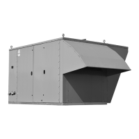
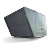
Energy Recovery Exhaust Option