29MCP15-500.7
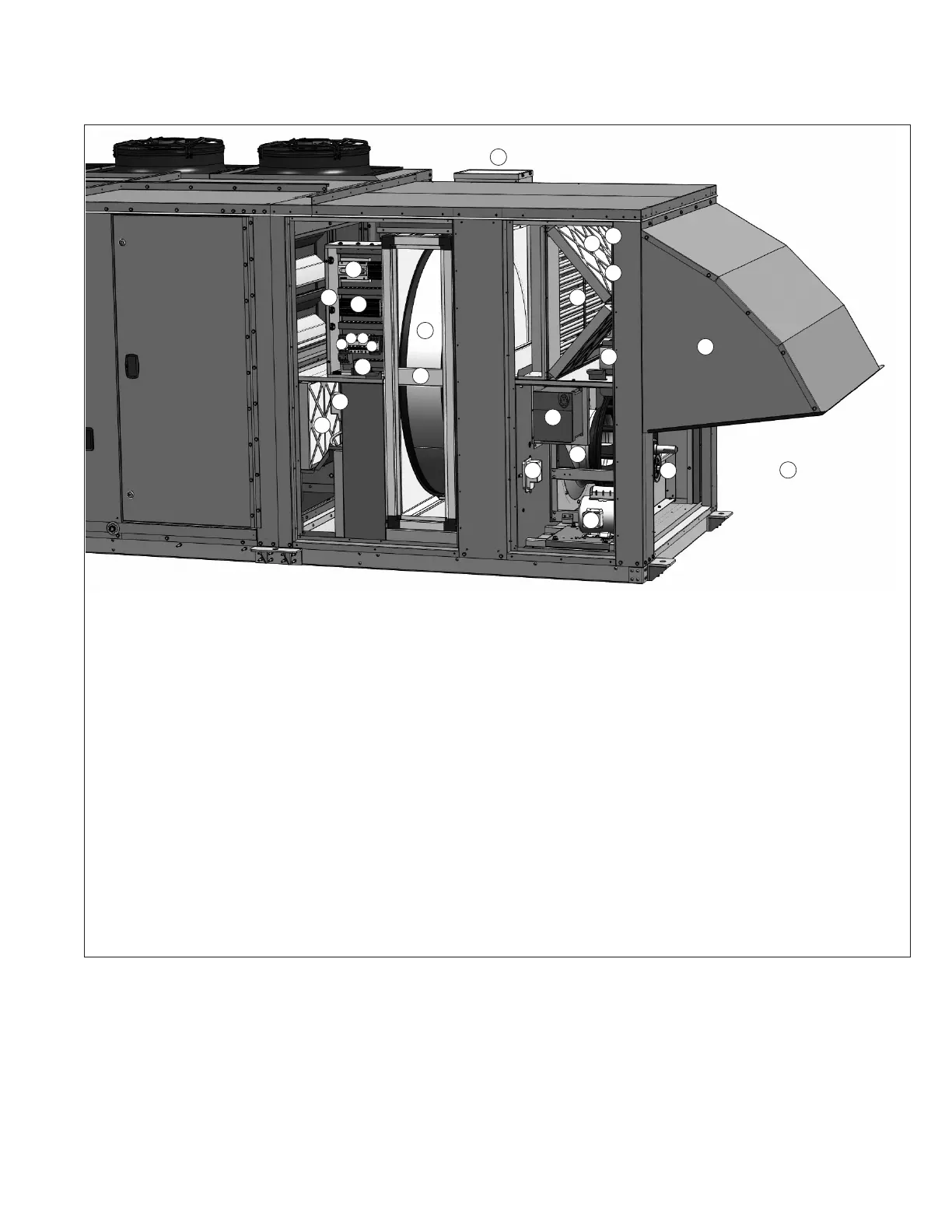
Figure 29.1 - Controls Cabinet - Energy Recovery Section (B-Cabinet only, if equipped) j
2 (S) Controls compartment with side wiring entrance
3 (S) Power distribution block
4 (S) Carel pCOxs microprocessor controller
5 (O) Exhaust fan motor starter (unless VFD controlled, see #19)
6 (S) Exhaust fan motor circuit breaker
7 (S) Energy recovery wheel drive motor circuit breaker
8 (S) Energy recovery wheel drive motor motor starter
9 (S) High and low voltage wiring terminal strip with ground
terminals
10 (O) Exhaust air filters
11 (O) Exhaust air filters pressure drop switch
12 (S) Energy recovery wheel
13 (O) Energy recovery wheel pressure drop switch
14 (O) Energy recovery wheel electric preheat assembly
with control compartment
15 (S) Outside air filters
16 (O) Outside air filters pressure drop switch
17 (S) Blower door switch
18 (S) Outside air enthalpy sensor
19 (O) Exhaust fan variable frequency drive (unless motor
starter controlled, see #5)
20 (S) Exhaust fan motor
21 (S) Exhaust fan plenum fan
22 (S) Exhaust fan belt drive/auto belt tensioner access (access
door removed)
23 (O) Inlet hood
24 (S) Exhaust hood (not pictured)
25 (O) Economizer bypass damper actuator compartment
26 (O) Energy recovery wheel rotation detection sensor
(not pictured)
(S) = standard (O) = optional
UNIT COMPONENT IDENTIFICATION / LOCATION
3
11
12
26
13
14
16
17
15
9
10
4
5
7
8
6
2
18
19
20
21
22
23
24
25
j Location of components is typical, but may change depending on the unit configuration.