3MCP15-500.7
TABLE OF CONTENTS / SI (METRIC) CONVERSION FACTORS / UNIT LOCATION
TABLE OF CONTENTS
Inspection on Arrival ............................................................ 1
Special Precautions ............................................................. 2
SI (Metric) Conversion Factors ........................................... 3
Special Design Requests .................................................... 3
Storage Prior to Installation ................................................. 3
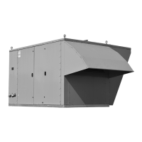
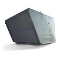
Unit Location ....................................................................... 4
Installation ......................................................................4-15
Combustible Material and Service Clearances .........4-5
Roof Curb Installation ................................................... 4
General Rigging Instructions/Unit Installation ...........6-7
Duct & Condensate Drain Installation .......................... 8
Electrical Connections .................................................. 9
Gas Connections ........................................................ 10
Vent Terminals and Combustion Air Hoods ................ 11
Gas Heating Option Condensate Drains & Traps ...... 14
Hot Water Piping Connections ...................................15
Start-Up Procedure ......................................................16-29
General. ...................................................................... 16
Blower Adjustments .................................................... 17
Airflow Proving Switch and Dirty Filter Switch............ 19
Variable Air Movement Applications ........................... 19
Checking Refrigerant Charge ..................................... 20
Gas Heating Option .................................................... 21
Energy Recovery Option (B-Cabinet units only) ........ 28
Unit Features/Options Location Drawings ....................30-35
Dimensions/Weights ....................................................36-44
B-Cabinet Size Unit without Energy Recovery. .......... 36
B-Cabinet Size Unit with Energy Recovery. ............... 38
C-Cabinet Size Unit .................................................... 40
D-Cabinet Size Unit .................................................... 42
Base Model Weights ................................................... 44
Option and Accessory Pressure Drop Tables ..............45-47
Maintenance .................................................................48-50
Service & Troubleshooting ...........................................51-55
Serial Plates ...................................................................... 56
Model Nomenclature ....................................................57-59
Commercial Warranty ...........................................Back Page
SI (METRIC) CONVERSION FACTORS
To Convert Multiply By To Obtain
"W.C. 0.24 kPa
psig 6.893 kPa
°F (°F-32) x 0.555 °C
inches 25.4 mm
feet 0.305 meters
CFM 0.028 m
3
/min
To Convert Multiply By To Obtain
CFH 1.699 m
3
/min
Btu/ft
3
0.0374 mJ/m
3
pound 0.453 kg
Btu/hr 0.000293 kW
gallons 3.785 liters
psig 27.7 "W.C.
Special Design Requests
Modine Manufacturing Company will sometimes build units
with special features as requested by the customer. This
manual only covers standard features and does not include any
changes made for special feature requests by the customer.
Units built with special features are noted with an SPO (Special
Product Order) Number on the Serial Plate
Storage Prior to Installation
If the unit is stored outside prior to installation, the unit should
be covered.
IMPoRtANt
eventually causing the drain pan to fill. To prevent
damage to the building or unit, a drain pan float switch
is included as standard and will disable the unit if the
maximum condensate level is reached.
3. To prevent premature heat exchanger failure, the input
to the appliance, as indicated on the serial plate, must
not exceed the rated input by more than 5%.
4. To prevent premature heat exchanger failure, check to
be sure the blower has been set to deliver the proper
airflow for the application. Refer to page 17 for Blower
Adjustments.
5. Start-up and adjustment procedures must be performed
by a qualified service agency.
6. All scroll compressors requires the correct supply power
phase rotation. Phase reversal may result in compressor
failure not covered under warranty. Refer to the Start-Up
Procedure section.
7. All refrigeration checks must be made by a qualified
R-410A refrigeration technician.
8. Do not release refrigerant to the atmosphere. When
adding or removing refrigerant, all national, state/
province, and local laws must be followed.
9. On units with the electric preheat option, to prevent
premature heat exchanger failure, check to be sure the
blower has been set to deliver the proper airflow for the
application. Refer to page 17 for Blower Adjustments.
10. The exhaust fan is not designed for high temperature
or smoke control exhaust applications. Exhaust air
temperature must not exceed 104°F. Operating the
exhaust fan above 104°F will result in failure of the
exhaust fan.