32 MCP15-500.7
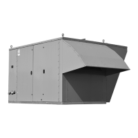
UNIT COMPONENT IDENTIFICATION / LOCATION
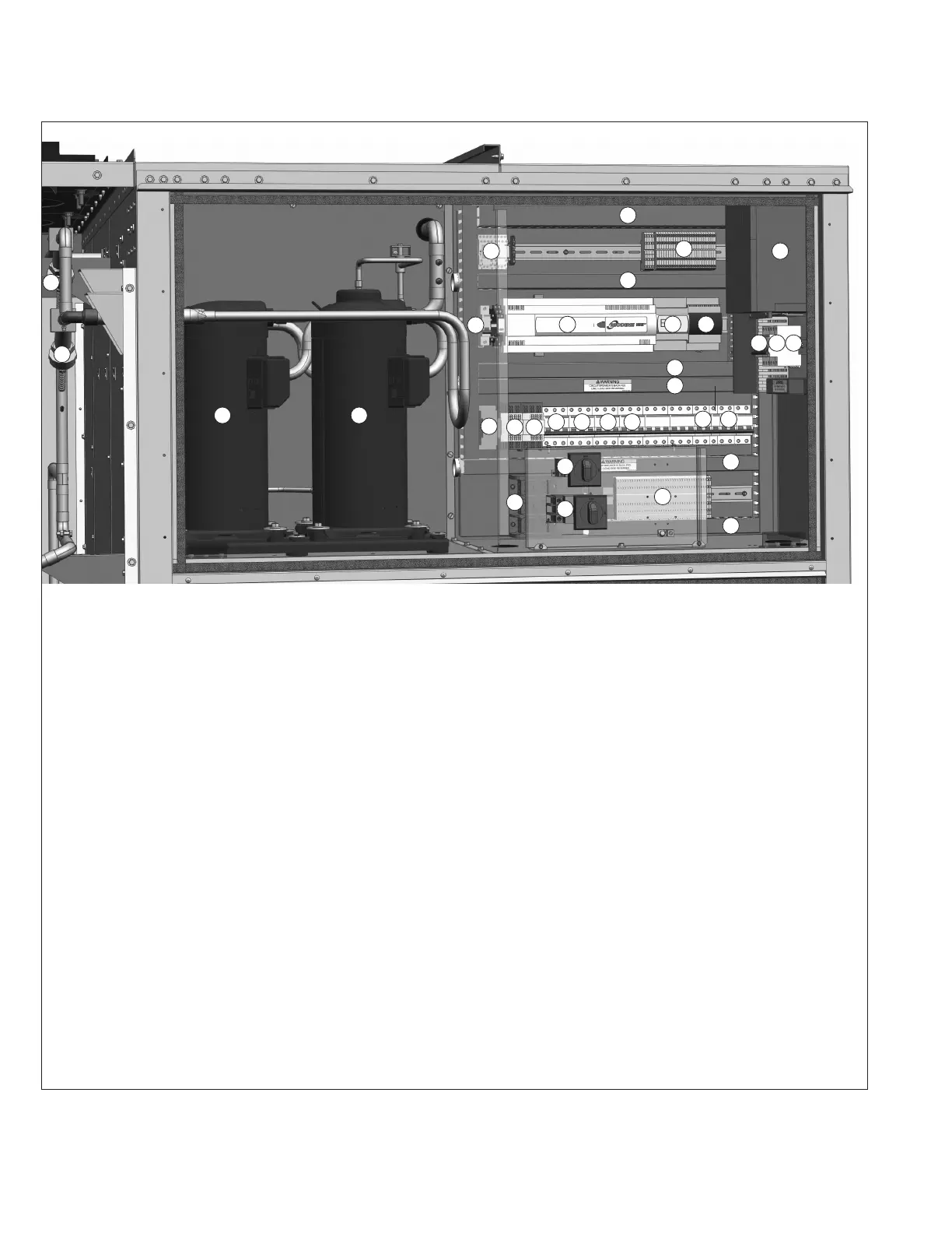
Figure 32.1 - Controls Cabinet - B-Cabinet Sized Units j
1 Not applicable
2 (S) Condenser fan motor circuit breakers
3 (O) Hot gas reheat circuit shut-off valves
(not shown, located in coil compartment)
4 (O) Hot gas reheat modulating valves
5 Not applicable
6 (S) Tandem digital scroll compressor set
(7 ton nominal units feature a single modulating digital
compressor, all others are tandem)
7 (S) Carel EVD superheat/electronic expansion valve controller
8 (S) Carel microprocessor controller (main)
9 (S) Carel Ultracap for EVD controller
10 (S) Low voltage wiring terminal strip with ground terminals
11 (S) Low voltage wiring channels
12 (S) Low voltage transformer for Carel microprocessor
controller (behind item 33)
13 Not applicable
14 (S/O) Double pole, double throw relay(s)
15 (S) High voltage wiring channels
16 (O) Supply voltage/phase monitor
17 (S) Condenser fan variable frequency drive circuit breaker
(not pictured, only applies to Model Digit 11=A or B)
18 (O) Supply fan variable frequency drive circuit breaker
19 (O) Power exhaust fan contactor/variable frequency drive
circuit breaker
20 (S) Main controls step-down transformer primary circuit
breaker
21 (O) Gas heating circuit step-down transformer primary circuit
breaker
22 (O) Convenience outlet step-down transformer primary circuit
breaker (if factory powered)
23 (O) Convenience outlet step-down transformer secondary
circuit breaker (if factory powered)
24 (S) Main controls step-down transformer secondary circuit
breaker
25 (S) High voltage wiring terminal strip with ground terminals
26 (S) High voltage power distribution block
27 (S) Compressor #1 contactor
28 (S) Compressor #2 contactor
29 (S) Condenser fan variable frequency drive
(not pictured, only applies to Model Digit 11=A or B)
30 (O) Supply fan variable frequency drive
31 (O) Gas heating circuit step-down transformer (behind item 33)
32 (O) Factory powered convenience outlet disconnect switch
33 (O) Main unit deadfront disconnect
(S) = standard (O) = optional
11
11
11
14
25
15
15
16
15
7 9
8
10
4
4
6 6
2 2 2 19
18 22 23
26
20
21
32
33
27 28
30
24
j Location of components is typical, but may change depending on the configuration of the unit.