35MCP15-500.7
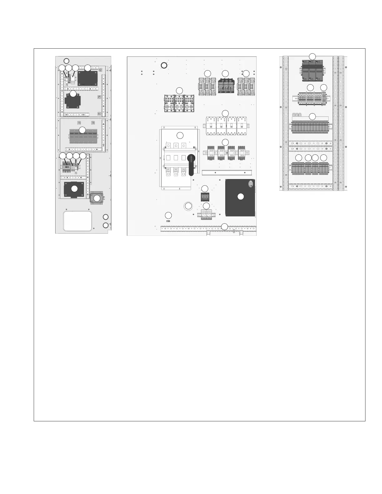
UNIT COMPONENT IDENTIFICATION / LOCATION
1. (O) Gas Heat Control Transformer Secondary Circuit Breaker
2. (O) Wiring Terminals for Item #1
3. (O) Phase Monitor Relay
4. (O) Gas Heat Control Transformer
5. (S) 24V Control Transformer
6. (O) Auxiliary Electric Heat (Gas Heat Option) Fuses
7. (O) Powered GFCI Convenience Outlet Option consisting of:
a. Disconnect Switch
b. Transformer Primary Fuses
c. Secondary Circuit Breaker
d. Terminal Strip
e. Transformer
f. Convenience Outlet Junction Box (outlet accessible from
Low Voltage Control Cabinet (see Figure 34.1))
8. (S) Main High Voltage Power Distribution Block
9. (O) Supply Fan VFD #2 Fuses (dual blower 15 or 20HP only)
10. (S) Compressor Power Distribution Block
11. (S) Supply Fan VFD #1 Fuses
12. (S) Compressor Circuit Breakers
13. (S) Compressor Contactors
3
7e
11
7f
14
26 27
15
16
8
9 10
4
5
6
2
17
21 22
18
20
23
24 25
14. (O) Main Factory Mounted Disconnect Switch
15. (S) Supply Fan Power Distribution Block (dual blower
1-10HP)
16. (S) Supply Fan VFD #1 (not pictured is Supply Fan VFD #2
for dual blower 15 or 20HP)
17. (S) Supply Fan Overloads (dual blower 1-10HP)
18. (S) Ground Lug
19. (S) Main Ground Bus Bar
20. (S) Sub Feeder Fuses
21. (S) Terminal Strip for Power Distribution
22. (S) Ground Terminal Blocks
23. (S) Condenser Fan Fuses and Bus Bar
24. (S) Compressor Crankcase Heater Fuses
25. (S) Control Transformer Primary Fuses
26. (O) Gas Heat Control Transformer Primary Fuses
27. (O) Phase Monitor Relay Fuses
28. (S) Cabinet Cooling Device
(S) = standard (O) = optional
j Location of components is typical, but may change depending on the configuration of the unit.
Figure 35.1 - Power Cabinet - D-Cabinet Sized Units j
1
7c7b7a 7d
12
13
19
28