Setup
05/06 AWB2724-1584GB
10
Example: If you are using input I1 for a high-speed counter (16-
bit), I2 can be used for another high-speed counter (16-bit) but not
for generating an interrupt. Inputs I3 and I4 likewise cannot be
used for generating an interrupt.
Connection description a figure 19 on page 20.
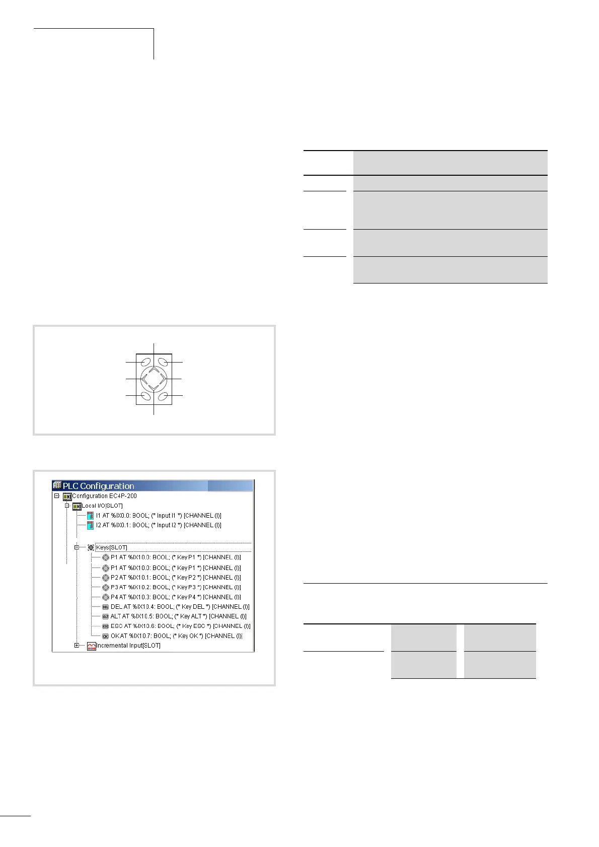
Inputs of the rocker and function buttons
The front plate of the device is provided with the function buttons
DEL, ALT, ESC, OK which are arranged around the rocker switch.
The rocker switch is divided into 4 sections with the designations
P1 to P4. The function buttons and the rocker buttons P1 to P4 are
represented in the PLC configuration as inputs. Their symbolic
names correspond to the name of the button or rocker section, e.g.
P1. These inputs are scanned in the program according to general
syntax rules. Only one button can be actuated at a time, otherwise
uncontrolled states may occur when the P buttons are scanned.
The “GetDisplayInfo” function block from the “EC_Visu.lib
library” enables you to control the scanning of the buttons
according to the active menu on the controller, a section
“EC_Visu.lib library”, page 52.
Diagnostics inputs
The inputs I13, I14, I15, I16 provide you with additional
information:
The inputs can be scanned in the program with symbolic operands.
Inputs for high-speed counters
You can choose between several different functions:
• 1 x 32-bit counters, for counting pulses (up/down)
• 2 x 16-bit counters, for counting pulses (up/down); the count
direction (up/down) can be set via the DIRECTION operand in
the program.
• 1 x incremental value counter, 32-bit, for processing the signals
of an incremental encoder; the count direction is set by the edge
sequence of the encoder.
You can select the counter type in the PLC configuration.
The function of the high-speed counter requires the setting of
inputs and the scanning of outputs in a POU, e.g. PLC_PRG.
This POU must not be called by an interrupt generated by a
counter.
For further information see section “High-speed counters”,
page 39.
Outputs
Table 2: Type and number of outputs
The transistor outputs are provided with a short-circuit monitoring
function . In the event that a short-circuit occurs at one of the
outputs, this is indicated via the diagnostics inputs I15/I16. I15 is
set to 1 if a short-circuit occurs at the outputs Q1 to Q4. Input I16
is toggled if a short-circuit occurs on Q5 to Q6.
Figure 4: Rocker switch with rocking ranges P1, P2, P3, P4
Figure 5: Inputs of the rocker and function buttons
P2
OK
P3
ALT
P4
ESC
P1
DEL
Input Function
I13 No function
I14 Connection to the expansion device via easy-Link (not yet
active in the operating system version 1.x):
0: ok, 1: not ok
I15 Outputs Q1, Q2, Q3, Q4:
0: No short-circuit, 1: Short-circuit
I16
Outputs Q5, Q6, Q7, Q8:
0: No short-circuit, toggle: Short-circuit
EC4P-221/222-MT…
transistor outputs
8 (Q1…Q8) 24 V DC/0.5 A
EC4P-221/222-MR…
relay outputs
6 (Q1…Q6) 250 V AC/8 A