Setup
05/06 AWB2724-1584GB
12
Real-time clock
The PLC is provided with a real-time clock that can be accessed in
the user program via functions from the “SysLibRTC library”. The
functions are described in the PDF file “SysLibRTC”. After the
software is installed, this file can be opened via <Programs l
Moeller Software l easy Soft CoDeSys l Documentation l
Automation Manuals>.
The clock can be read or set using the browser command “getrtc”
and “setrtc”. More information is provided in section “setrtc” on
page 50.
The clock is backed up for at least 72 hours in the event of a power
failure.
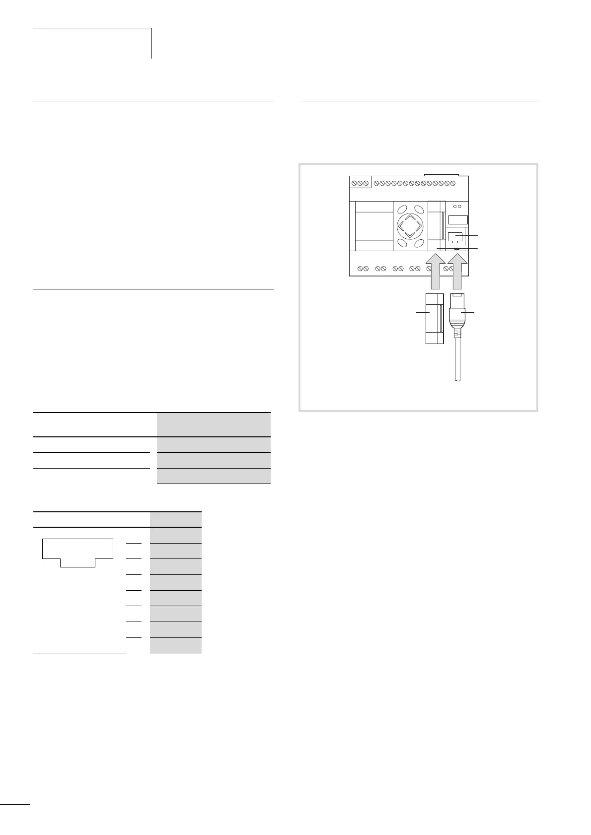
Programming interface for the PC
To connect the controller with a PC, use the cable EU4A-RJ45-
CAB1. The cable should be plugged into the programming
interface (RS232) of the controller. The interface is not electrically
isolated.
The interface is initialised with the following default parameters
when the PLC is started.
Table 5: Default parameters of the RS232 interface
Table 3: Pin assignment of the RS232 programming interface
Transparent mode
The programming interface is addressed as COM1. It can be
switched to Transparent mode using the functions of the library
EC_SysLibCom.lib.
a chapter “RS 232 interface in Transparent mode”, page 63.
Universal interface
This interface is used for communication between the PLC and a
memory card. The memory card should be fitted in an adapter
which is then fitted on this slot.
a Programming interface for connection to a PC
b Universal interface
c EU4A-RJ45-CAB1 cable
d Adapter with memory card
Data length
8 Bit
Parity None
Stop bits
1
Baud rate
38400 Baud
Signal
1
–
2
–
3 –
4
GND
5
TxD
6
–
7 GND
8 RxD
12345678
Figure 6: Universal interface/Memory card socket
RUN
STOP
SF
CAN/
NET
a
b
PC
(RS 232)
c
d