05/06 AWB2724-1584GB
62
Example: Accessing a PLC program
The example below illustrates the procedure for accessing a PLC
program.
You have connected the PC to the PLC with Node ID “2” and want
to access the target PLC with Node ID “3”.
X Open the project of the target PLC (Node ID 3) which has the
program you wish to edit or test.
X First configure the parameters for the hardware connection PC
n PLC (Node ID 2).
X From the Online menu select “Communication Parameters”....
X Click the New button under Local channels.
The “New Channel” window appears.
X Select the channel in the “Device field”.
XC200: Serial [RS232] [Level 2 Route] or TCP/IP [Level 2 Route].
X You can assign a new name in the “Name” field, e.g.
“Rout_232”.
X Confirm with OK. You will return to the initial window.
You have now defined the parameters for the hardware
connection between the PC and the PLC (Node ID 2).
X Call up the communications parameters in the “Online” menu
once again and select the PLC which you want to program/test.
X Enter the target ID, number 3 in the example. The target ID is
the same as the Node ID! To enter the target ID click on the field
in the “Value” column next to the word Target ID. Enter the
number 3 and confirm with OK.
X Log on and carry out the action.
PLC combinations for routing
The following PLCs support routing:
Number of communication channels
Several communication channels can be opened, e.g. PC n PLC
2, PC n PLC 3 in dependence on the PLC (communication
channel) which is connected to the PC. The status display of
control 2 and 3 can be implemented simultaneously.
Table 12: Type and number of communication channels depending on
the PLC
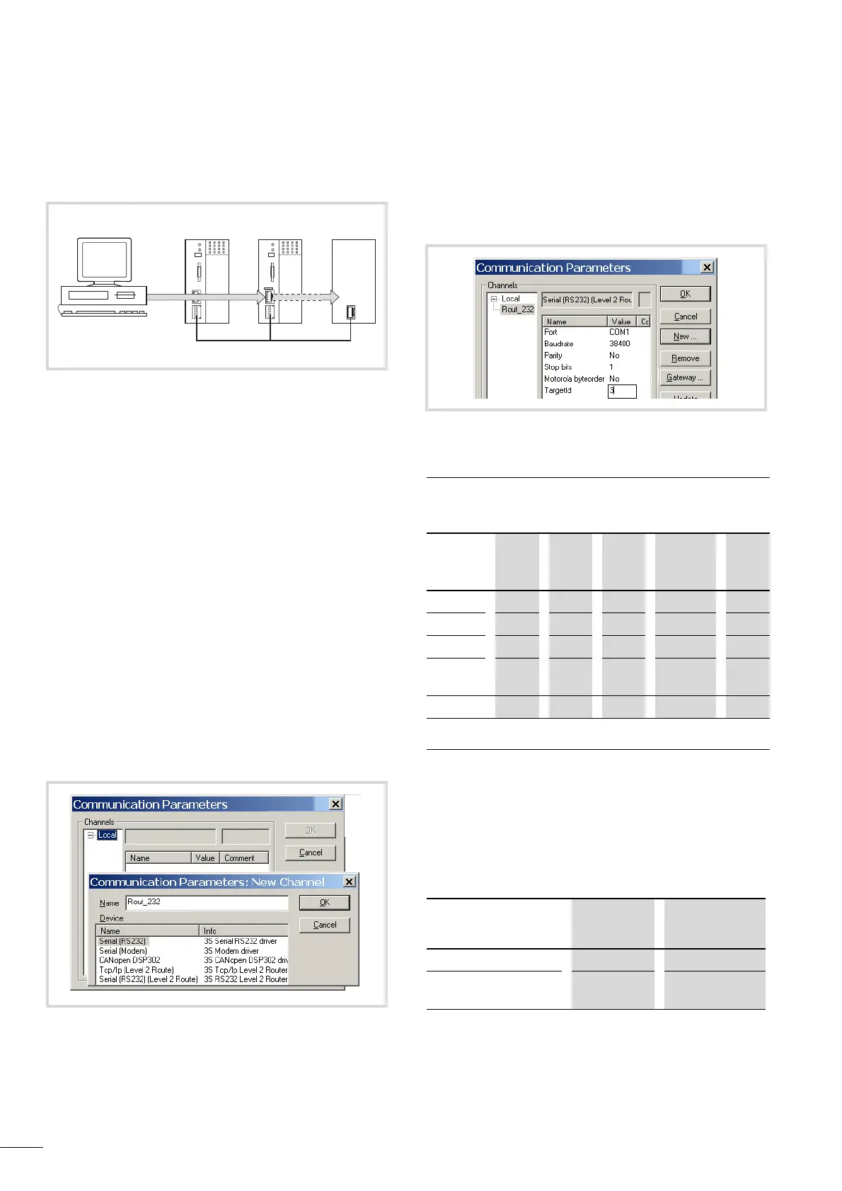
Figure 77: Diagnostics options
a XC100 with Node ID 1
b XC200 with Node ID 2
c Controller with node ID 3, e.g. XC100,XC200,XC121, XN-PLC,
EC4-200.
Figure 78: Setting channel parameters
abc
CANopen
Figure 79: Setting the target ID of the target PLC
From P
XC100 XC121 XC200 XN-PLC-
CANopen
EC4-
200
To O
XC100 x x x x x
XC121
x x x x x
XC200
x x x x x
XN-PLC-
CANopen
x x x x x
EC4-200
x x x x x
Communications
channel
PLC Max. channel
count
TCP/IP Level2Route XC200 5
Serial RS232 Level2Route XC100/XC200/
XN-PLC
1