Features & Description
EPM2000/EPM2000e Reference Guide
5
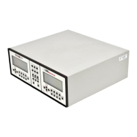
Figure 1: Pulses which will or will not trigger the EPM2000 Internal trigger.
The ranges differ by powers of ten. A full-scale signal on one range may not trigger on the next
higher range unless the trigger level is set to less than 10%. For example, a near full-scale signal of
280 mJ on the 300 mJ range is less than 10% of full scale on the next higher range (2 J) and would
not trigger the reading, so adjust the trigger level to less than 8% for reliable triggering.
The trigger is synchronous with the leading edge of the pulse, but the actual peak is determined
algorithmically by sampling the input signal near the trigger. From the trigger point forward, the
algorithm searches for peaks and from the trigger point back, it searches for a baseline.
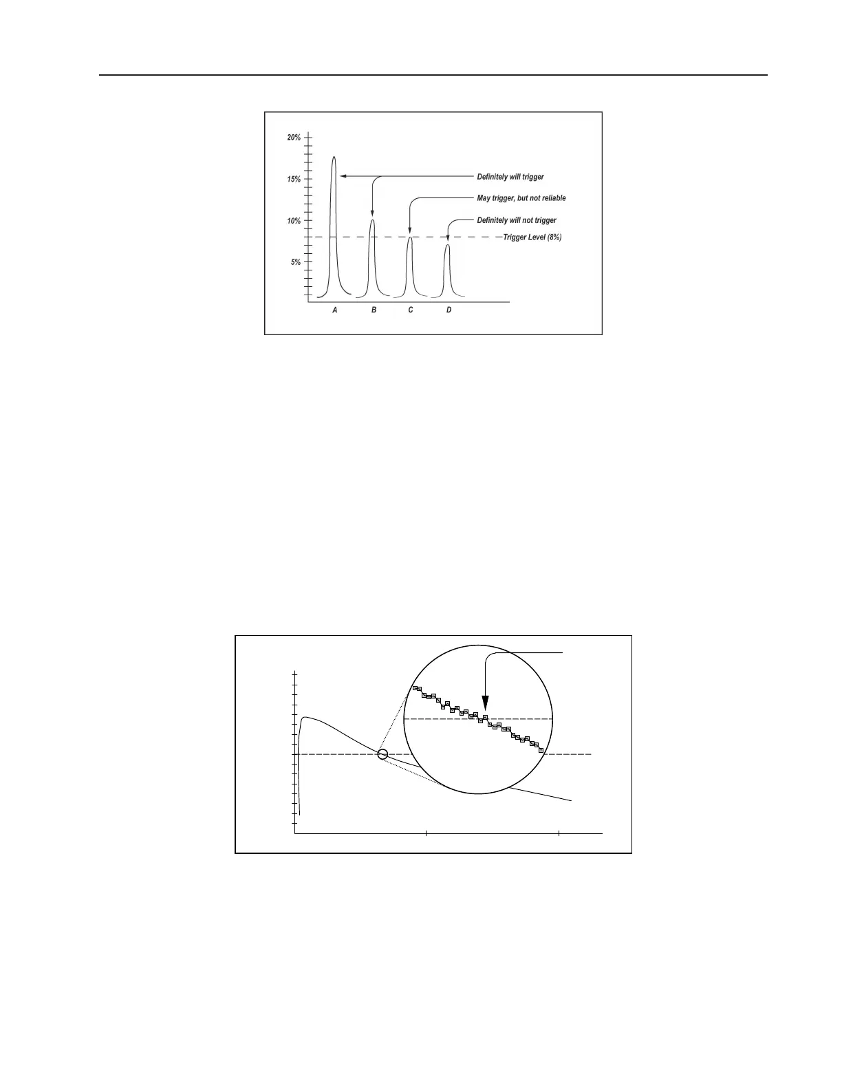
The EPM2000 can be programmed to ignore triggers for a specified time after a valid trigger. This
prevents “false” triggers in pulse tails from accidentally starting a new sample (see Figure 2). This
amount of delay time is called the Trigger Holdoff (see Operation -- Settings -- Trigger Holdoff).
The EPM2000 is set at the factory with a 0 ms trigger holdoff.
5%
10%
15%
Trigger
Level
Possible
False
Trigger
1 ms 2 ms
Figure 2: How a false trigger could occur.