Features & Description
EPM2000/EPM2000e Reference Guide
6
UNDERSTANDING THE EPM2000 EXTERNAL TRIGGER CIRCUIT
The Circuit
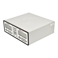
Each External Trigger of the EPM2000 is a 100 W resistor in series with an optical coupler. The
coupler is protected by an additional diode (see Figure 3). A rising edge at the Trigger In BNC
forward biases the optocoupler diode and triggers the channel. If the EPM2000 channel is set for
EXT NEG trigger, then the same sequence is initiated by a falling clock edge.
Figure 3: The external trigger circuit for the EPM2000.
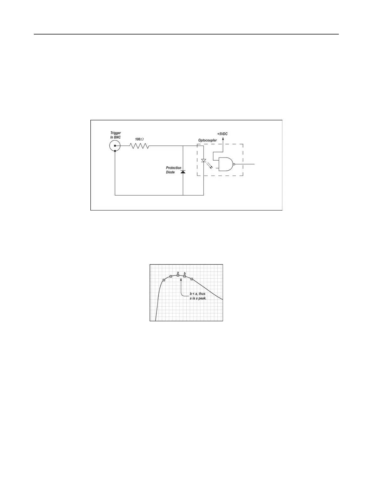
The EPM2000 searches for a peak as soon as it receives the trigger signal. It compares successive
A/D conversions, defining a peak as the first value followed by a lesser value, as shown in Figure 4.
This allows the EPM2000 to read very long pulses with well-behaved rise characteristics.
Figure 4: Determining a peak.
Trigger the EPM2000 as close to the pulse as possible. If the EPM2000 is triggered too early, it will
detect fluctuations in the noise preceding the pulse and derive a false peak.