Features & Description
EPM2000/EPM2000e Reference Guide
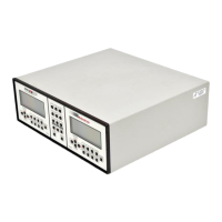
9
Smart Probe Connectors
These connections are for all of Molectron’s PowerMax probes, as well as specially powered
Joulemeter probes.
Pulse In Connectors
Pulse In connects pyroelectric laser energy probes and are internally terminated with 1MΩ
impedance. Probes with 50 Ω impedance (such as J3, J3S, and J4 probes) must use a 50 Ω feed-
through terminator, available through Molectron Detector, Inc., or equivalent to Pomona P/N 4119.
Analog Out Connectors
These connections provide an output voltage into loads ≥ 600 W that is proportional to the input pulse
amplitude, scaled to the full scale of the display. The output range is 0 to V
max
VDC, where V
max
is
defined in Figure 8. R
load
is the impedance of the monitoring device (oscilloscope, A/D converter,
etc.). The outputs update three times per second. Note that, although in some instances the
EPM2000’s display will exceed the selected range, under no circumstances will the output value
exceed V
max
.
Figure 8: Conversion formula for Analog Out levels.
Trigger In Connectors
These inputs accept synchronized pulses from the laser. They are electrically isolated from the
EPM2000 and consist of a 100 Ω resistor in series with an optoisolator. They can be set from the
front panel or via remote to trigger on the rising or falling edge of the input signal. They only trigger
pyroelectric/silicon measurements.
RS-232 Interface
The EPM2000 acts as a DTE (Data Terminal Equipment) device through this 9-pin RS-232
connector. It mates with a standard 9-pin straight-through serial cable to a typical IBM-AT
compatible PC, or other DCE (Data Communications Equipment) device. Hardware handshaking is
implemented.
Pin Assignment
1 DCD (not used in the EPM2000)
2 RXD
3 TXD
4 DTR
5 GND
6 DSR
7 RTS
8 CTS
9 RI (not used in the EPM2000)
Table 1: RS-232 pin assignments.