5. Setting up the device
26
Menu level Parameterisation level
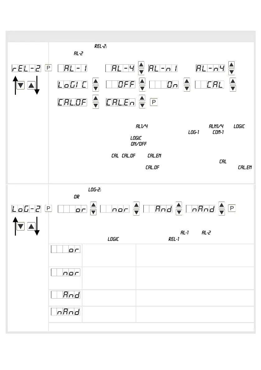
Alerting relay 2,
Default:
Each setpoint (optional) can be linked up via 4 alarms (by default). This can either
be inserted at activated alarms or deactivated alarms . If is
selected, logical links are available in the menu level and . Access to
these two menu levels is via , at all other selected functions, these two
parameters are overleaped. Via the setpoints can be activated/deactivated,
in this case the output and the setpoint display are set/not set on the front of the
device. The parameters , and can only be used in accordance with
the semi-automatic calibration (Chapter 8. Sensor alignment). At the relay
switches during sensor calibration, at during offset calibration and at
during the calibration of the final value. With [P] the selection is confirmed and the
device changes into menu level.
Logic relay 2,
Default:
Here, the switching behavior of the relay is defined via a logic link, the following
schema describes these functions with inclusion of and : This parameter
can only be selected if was selected under .
A1 v A2 As soon as a selected alarm is activated, the
relay operates. Equates to operating current
principle.
A1 v A2 = A1 Λ A2 The relay operates only, if no selected alarm
is active. Equates to quiescent current
principle.
A1 Λ a2 The relay operates only, if all selected alarms
are active.
A1 Λ A2 = A1 v A2 As soon as a selected alarm is not activated,
the relay operates.
With [P] the selection is confirmed and the device changes into menu level.
____ _ _
____ _ _
….
….