16
Rev. 1.0
09/27/2023
400-820-9661
Multi-axis Series Hardware Manual
2.4 Connecting the EtherCAT
Dual RJ-45 connectors accept standard Ethernet cables and are categorized as 100BASE-TX
(100 Mb/sec) ports. CAT5 or CAT5e (or higher) cables should be used. The IN port connects to a
master, or to the OUT port of an upstream node. The OUT port connects to a downstream node.
If the drive is the last node on a network, only the IN port is used. No terminator is required on the
OUT port.
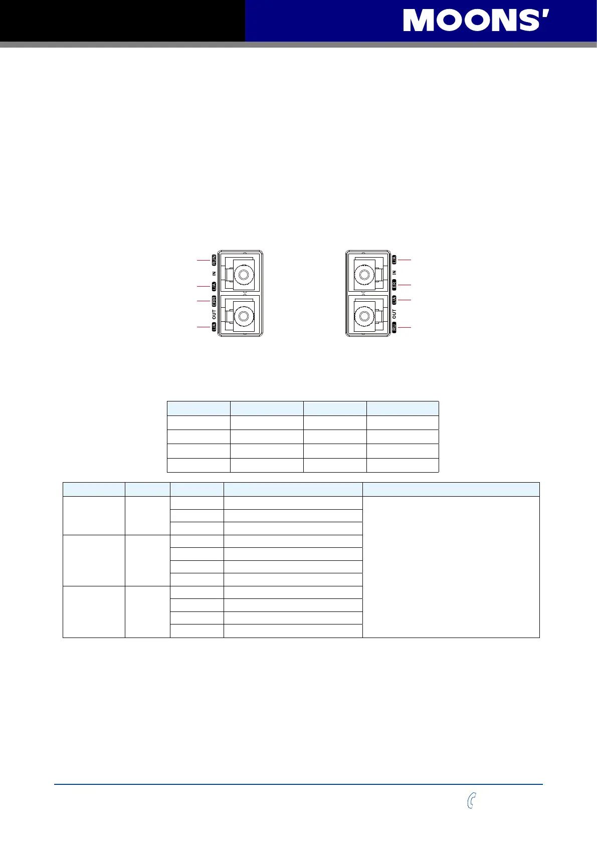
2.4.1 EtherCAT Status Indicator LEDs
The LEDs are used for indicating status of the EtherCAT. STF05/10-ECX-H included two Link/
Activity LED(the right one of every RJ-45), two EtherCAT status LED(RUN and ERR)
L/A OUT
ERR
L/A IN
RUN
X3
X4
X5
X7
X8
XCOM
Y1
Y3
YCOM
24V+
BRAKE
24V-
L/A OUT
ER
L/A IN
RU
SSDC06/10-4X-ECX SSDC06/10-2XU-ECX
SSDC06/10-4XU-ECX
pin Signal Definition pin Signal Definition
1 TX+ 5 (NC)
2 TX- 6 RX-
3 RX+ 7 (NC)
4 (NC) 8 (NC)
LED Color Status Description Instruction
Link/Activity Green
OFF no Ethernet connection
Flickering:
reveal 50ms,drown 50ms(10Hz)。and so
on.
Blinking:
reveal 200ms,drown 200ms(2.5Hz)。and
so on.
Single Flash:
reveal 200ms,drown 1s。and so on.
Double Flash:
reveal 200ms,drown 200ms,reveal
200ms,drown 1s。and so on.
ON Ethernet is connected
Flickering activity on line
RUN Green
OFF initialization state
Blinking pre-operational state
Single Flash safe-operational state
ON operational state
ERR Red
OFF no error
Blinking general error
Single Flash sync error
Double Flash watch dog error