25
Rev. 1.0
09/27/2023
Multi-axis Series Hardware Manual
400-820-9661
3.4.5 Logical relationship between STO function and input signal
SF1 input state SF2 input state STO functional state
ON ON no-trigger
ON OFF trigger
OFF ON trigger
OFF OFF trigger
Note: Conduction ON input voltage requires 24VDC, (each input signal has a minimum current
capacity of 5mA) OFF The input voltage must be 0 to 5VDC or left blank.
4 Mounting the Drive
The SSDC multi-axis series drives can be mounted through the narrow sides of the heat sink
using M3 or M4 screws. If possible, it is best to secure the drive to a smooth, flat metal surface,
which helps to dissipate heat from the drive. If this is not possible, it may be necessary to dissipate
heat through a fan to avoid overheating the drive.
• Do not install the driver in a place without ventilation or where the ambient
temperature is higher than 40
℃
.
• Do not install the driver in a humid area, or where metal debris or other conductive
objects can easily enter the driver and cause a short circuit.
• Ensure that there is sufficient airflow around the drive.
• When installing multiple SSDC drives, ensure that the space distance between the
drives is at least 2cm.
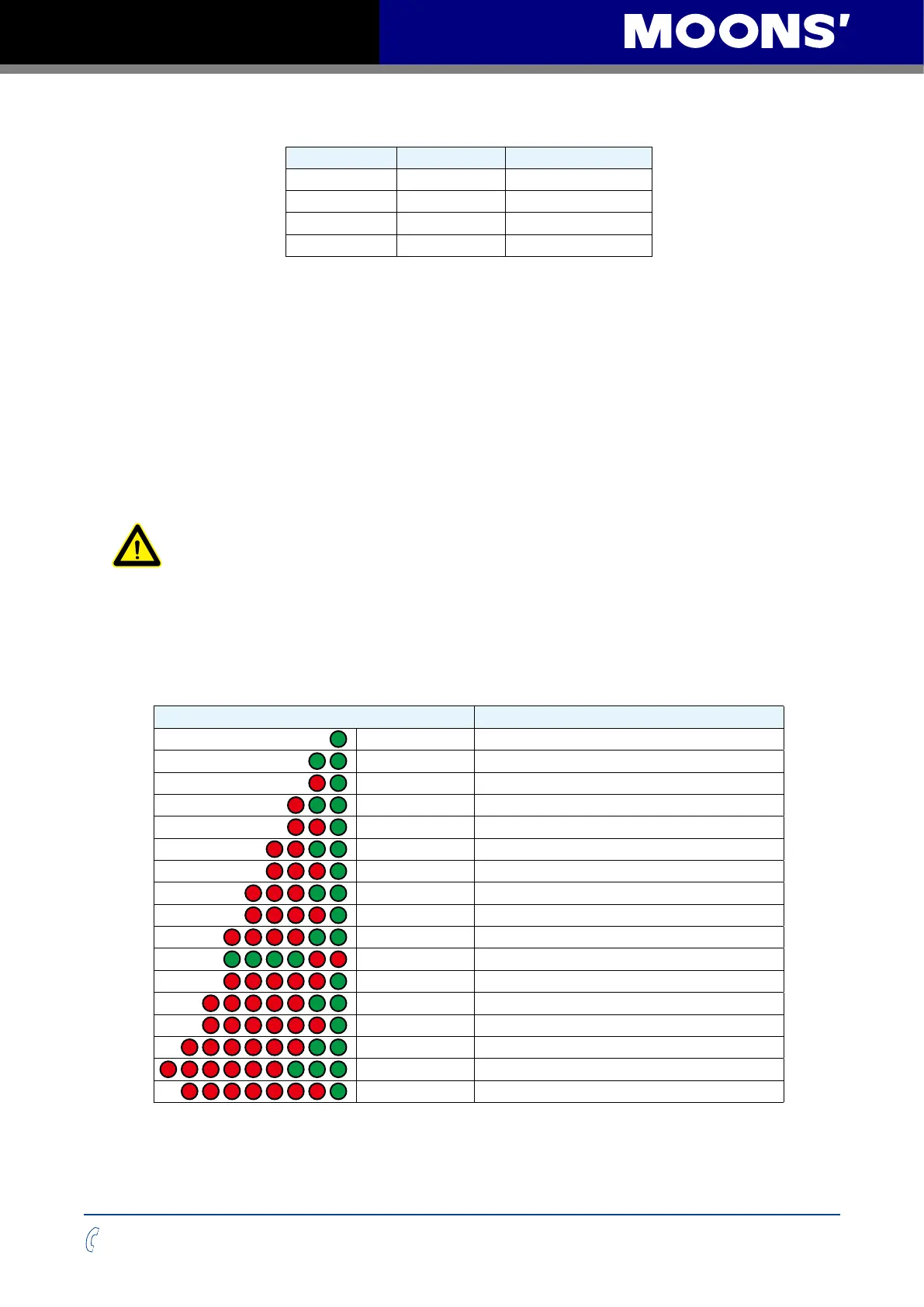
5 Alarm Code
Code Error
Solid green
No alarm, motor disabled
Flashing green
No alarm, motor enabled
1 red, 1 green
Position limit
1 red, 2 green
Move while disabled
2 red, 1 green
CCW limit
2 red, 2 green
CW limit
3 red, 1 green
Drive over temperature
3 red, 2 green
Internal voltage out of range
4 red, 1 green
Power supply over voltage
4 red, 2 green
Power supply under voltage
4 green, 2 red
EC dropout alarm
5 red, 1 green
Over current
5 red, 2 green
Current foldback
6 red, 1 green
Open winding
6 red, 2 green
Bad encoder
6 red, 3 green
STO Triggered
7 red, 1 green
Communication error
Note: An alarm in italics indicates that the drive is faulty and the motor enters the disabled state