24
Rev. 1.0
09/27/2023
400-820-9661
Multi-axis Series Hardware Manual
3.4.3 STO function precautions
1) If you do not need to use the STO function, please ensure that the STO docking terminal
equipped with the factory is correctly inserted in the port
2) To use the STO function, please make sure to understand the working mechanism and safety
precautions of STO
3) After triggering the STO function, due to the presence of external forces (such as vertical axis
load), the motor will rotate due to external forces. Therefore, ensure that the stepper/stepper servo
motor with brake is used in this case and the brake control circuit is properly connected
4) After triggering the STO function, the motor will stop freely, so it should be noted that the
stopping distance will increase under the action of inertia
5) After triggering the STO function, please note that the drive internal power tube will be cut off
the output, but the drive power will not be cut off. Therefore, ensure that the power supply is cut off
when troubleshooting.
6) After the STO function is triggered, the driver will be in the alarm state and the motor will not be
enabled.
7) After the STO input signal is restored to normal, the drive will still be in the alarm disabled state.
8) If the STO is triggered during the operation of the motor, the regeneration voltage may be too
large due to the large size of the motor frame or the high speed of the motor, which may lead to
the damage of the drive. In this case, in order to prevent damage due to regenerative voltage,
please connect our regenerative resistor RC880.
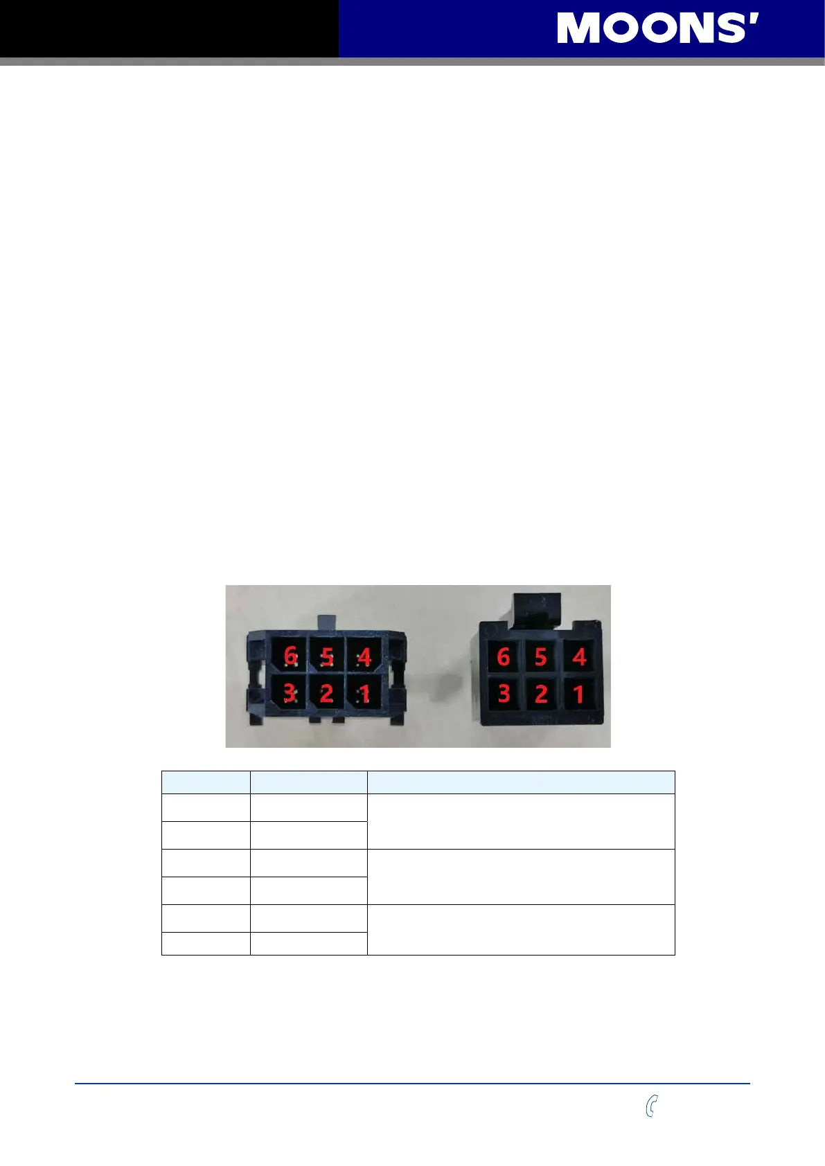
3.4.4 STO function pin definition
Signal Name connectorsPin No. Function
SF1+ 6
Input 1 for triggering the STO function
To trigger the STO function, turn off the optocoupler of
this input circuit.
SF1- 3
SF2+ 5
Input 2 for triggering the STO function
To trigger the STO function, turn off the optocoupler of
this input circuit.
SF2- 2
V+ 4
Power supply for drive outputs
For applications where the STO function is not used and
you do not want to connect a safety input signal.
V- 1