22
Rev. 1.0
09/27/2023
400-820-9661
Multi-axis Series Hardware Manual
3.2 Digital Outputs
The SSDC multi-axis series drives contain either 1 (-2XU/4XU) or 2 (-4X) digital isolated outputs. The
function of each output signal can be configured by the software Stepper Suite, and the output signal
corresponds to the function as follows:
signa
interface Function
Y1
Y1, YCOM
The following functions are available as options:
●
Driver error signal output
●
Driver error signal output
●
Static in place signal output
●
Dynamic in-place signal output
●
General-purpose output (default)
Y3
(
only--4X
)
Y3, YCOM
The following functions are available as options:
●
Pulse signal output (Tach Out)
●
Static in-place signal output
●
Dynamic in-place signal output
●
General-purpose output (default)
Please use Stepper Suite software to configure Y1,Y3 functions.
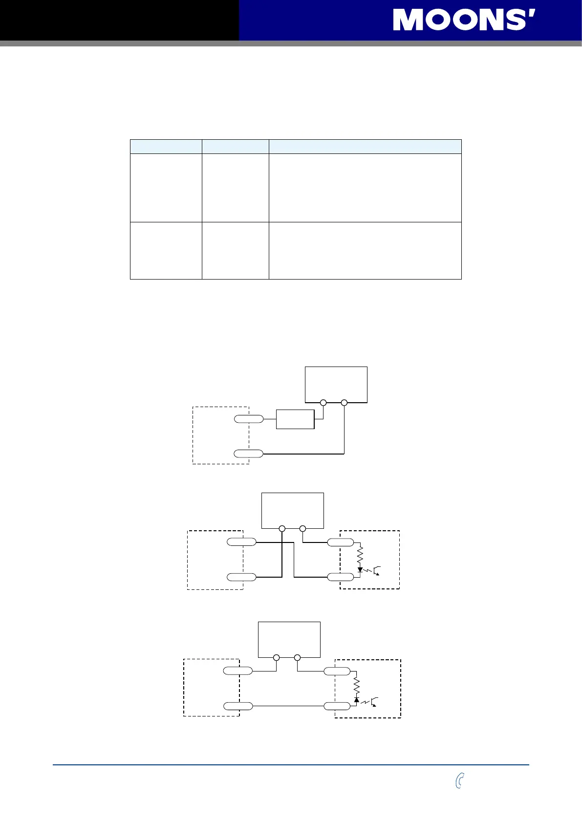
The following figure lists the common wiring methods of Y1 and Y3 output:
Warning: Do not connect the output to DC voltage above 30V, and the current flowing into the output
should not exceed 100mA
+ –
YCOM
YCOM
YCOM
Y1/Y3
Y1/Y3
Y1/Y3
CLP
+ –
IN
COM
PLC
+
–
COM
IN
Connecting a sourcing output to load
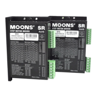
Connecting a sourcing output to PLC's input
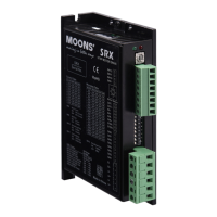
Connecting a sinking output to PLC's input
SSDC
SSDC
SSDC
5 - 24V
Power Supply
5 - 24V
Power Supply
5 - 24V
Power Supply
Load