www.miinet.com Moore Industries-International, Inc.
- 16 -
User’s Manual
225-748-00P
August 2024
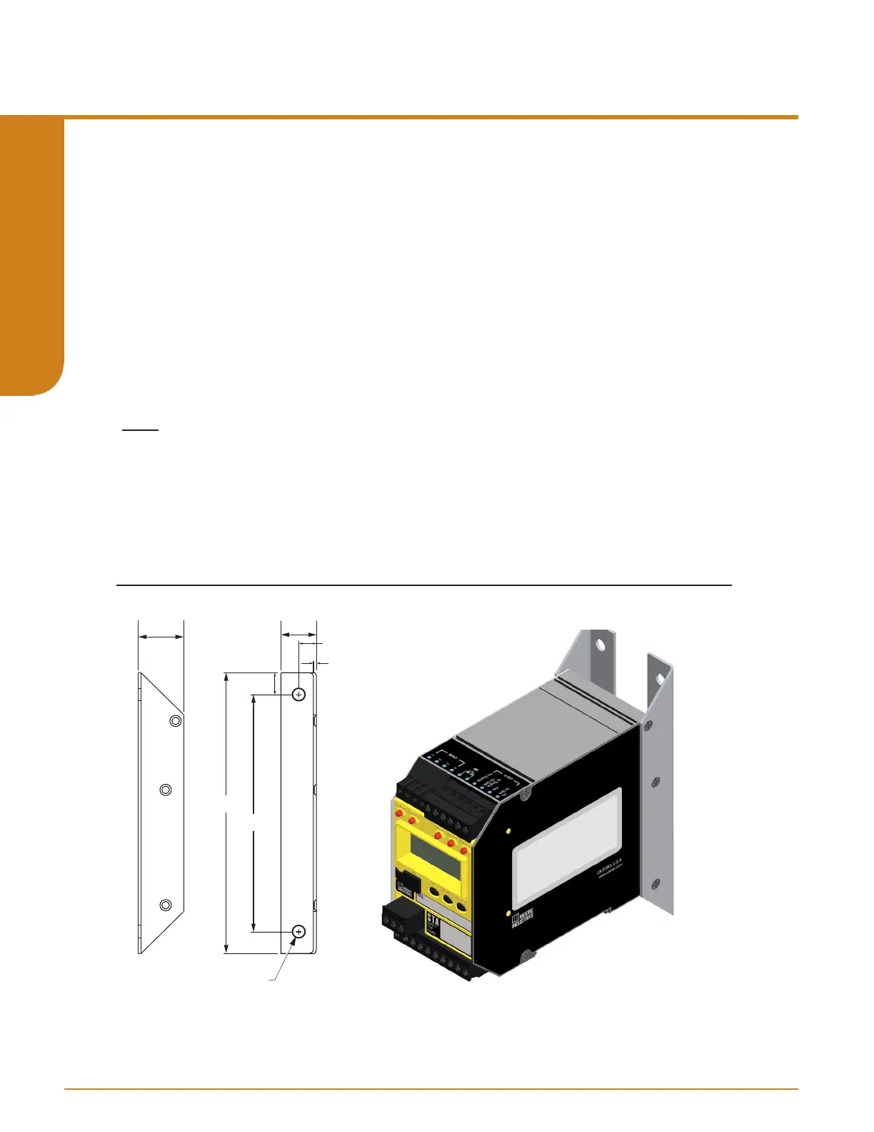
Figure 3.2. FLB ange bracket dimensions.
Mounting
The STA is housed in a DIN case that can be mounted on 35mm Top-Hat (EN50022) DIN-rail. To
mount the STA on a Top-Hat DIN-rail, seat the upper extrusion on the unit back panel over the top
lip of the rail and pivot downward until the housing locks into place. When mounting multiple units,
like a rack or cabinet, make sure to allow adequate vertical spacing for pivoting the units.
A ange bracket option is also provided as a secure mount for high vibration applications.
Reference gure 3.2 below.
Removal
To remove the STA from DIN rail you will need a simple tool such as a straight blade screwdriver.
Insert the blade of the screwdriver into cavity at the bottom of the locking mechanism and rotate
it. This will release the locking mechanism from DIN rail and allow you to remove the STA.
Note: The STA shall be installed in compliance with the enclosure, mounting, spacing and
segregation requirements of the ultimate application. Electronic components must be mounted
in a suitable enclosure.
23mm
(0.9 in)
18mm
(0.7 in)
9mm
(0.4 in)
2 mm
(0.1 in)
11mm
(0.4 in)
143mm
(5.6 in)
121mm
(4.8in)
Ø6mm
(Ø0.3 in)
Programmable RTD, T/C, Ohms, mV and Potentiometer Safety Trip Alarm
STA
TPRG
SECTION 3