www.miinet.comMoore Industries-International, Inc.
- 63 -
User’s Manual
225-748-00P
August 2024
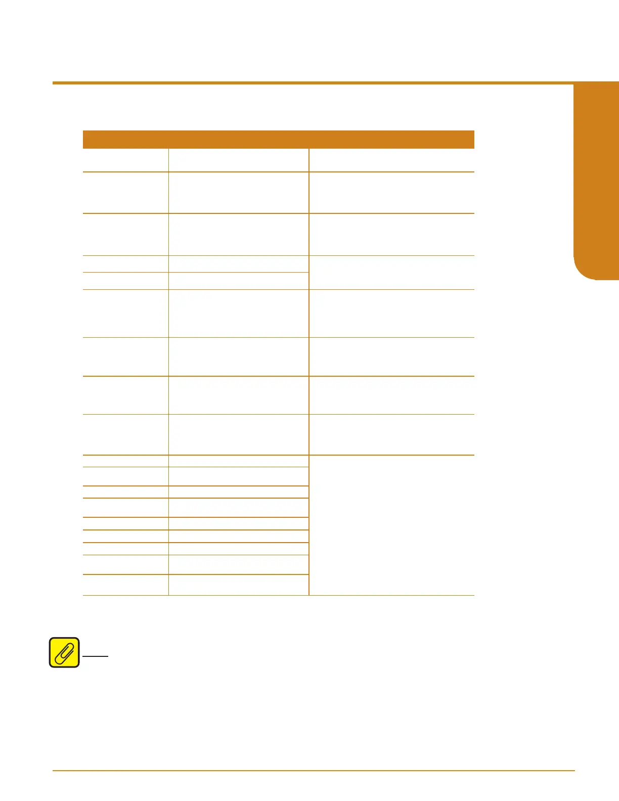
What it Means
What to Do
Error Message
SYS INIT
The system is completing initialization
The configuration stored in non-volatile
memory is invalid
User has reconfigured the unit with an
illegal configuration
A specific wire was detected as broken
Undetermined wire broken
The measured resistance / voltage was
outside the RTD or Thermocouple
table’s range
Input saturation condition (input reached
110% of calibrated range)
Input has gone outside the legal range
(as defined by the input LRV and URV
by more than 1%)
Excessive lead resistance
Note: This error only applies to 3-wire or
4-wire RTD sensors.
Calibration data is bad
Wait. Operation should commence in a few
seconds.
Using the menu system, trigger the unit to use the
FCTRY CONFG selection in the options menu
causing it to reset to factory configuration. Next
configure as appropriate for the application.
Usually caused by changing the input range, or
scaled range such that the trip points and/ or
deadband settings have become illegal.
Reconfigure with legal values.
Repair the broken wire(s), and use the menu
system or STA Configuration Software to RESET
FAULTS or cycle power.
Check the input and/or the selected input mode/-
sensor type (specifically a RTD’s alpha value),
and use the menu system or STA Configuration
Software to RESET FAULTS or cycle power.
Check the input signal to ensure that it is within
the sensor limits and use the menu system or
STA Configuration Software to RESET FAULTS or
cycle power.
Check the input and/or the input Upper and Lower
Range settings and use the menu system or STA
Configuration Software to RESET FAULTS or
cycle power.
Check sensor lead resistance. A resistance over
35 ohms is excessive (5 ohms for the Cu RTD).
Use the menu system or STA Configuration
Software to RESET FAULTS or cycle power.
These errors are generated by internal
diagnostics (see STA Diagnostics and Fault
Alarms p7). Spurious errors that could be caused
by external factors like transients or surges, may
result in a diagnostic failure and trigger the fault
alarm. Cycle power to the unit to clear the latched
fault alarm. If the error persists, then please
record the error message and contact Moore
Industries Customer Support for further
assistance.
ERROR CKSUM
ERROR CONFIG
WIREn BROKE
ERROR OUTOF/
LIMIT
WIRES BROKE
ERROR INSAT
ERROR OOR
ERROR CALIB
General ADC failure
ERROR ADC _ _ *
Fault alarm failure
ERROR RLAYF
Trip alarm 1 hardware failure
ERROR RLAY1
Trip alarm 2 hardware failure
ERROR RLAY2
General software failure detected by
diagnostics
General hardware failure detected by
diagnostics
ERROR SW _ _ _ *
ERROR HW _ _ _ *
Reference Junction Compensation RTD
burnout
ERROR RJC
Factory information is bad
ERROR FCTRY/
INFO
ERROR LINE/
RES
Table 6.1. STA Diagnostic messages and corrective actions messages
* Error messages ERROR ADC, ERROR SW, and
ERROR HW will also include a 2 or 3 digit sux. Moore
Industries Customer Service Technicians will use these codes to help determine the origin of the error.
Note: The Manual Reset (MR) will only reset Input Faults if configured in the Alarms Menu.
Maintenance
Moore Industries recommends that the calibration of this instrument should be checked every
year and re-calibrated only when necessary. In addition, we suggest a quick check for terminal
tightness and general unit condition. Always adhere to any site requirements for programmed
maintenance.
Programmable RTD, T/C, Ohms, mV and Potentiometer Safety Trip Alarm
STA
TPRG
SECTION 6