www.miinet.comMoore Industries-International, Inc.
- 23 -
User’s Manual
225-748-00P
August 2024
Programmable RTD, T/C, Ohms, mV and Potentiometer Safety Trip Alarm
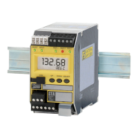
STA
TPRG
SECTION 4
Section 4 - STA Front Panel Conguration
The STA
(TPRG) operating parameters are set using the pushbuttons found on the instrument’s
front panel or STA Conguration Software. This section describes the steps in order to congure
your STA using Front Panel pushbutton method.
Front Panel Push Button Configuration
There are three pushbuttons on the unit’s front panel; UP, DOWN and SELECT. Together with
the prompts displayed on the LCD, these are used to access menus, and to view and change the
settings.
Use SELECT as your “Enter” button, to make your selections.
Use the UP and DOWN buttons to navigate within the menus.
View Menu
Figure 4.1 gives an overview of the View menu.
Upon power-up, the STA displays a ‘SYS INIT’ message until the power up self test is complete.
In normal operation the View menu will display the variable as configured. This can be the
process variable, the analog output variable, or both being toggled (Refer to Configuring the
Options Menu for more details).
1. From the display, press DOWN.
2. If the -AO option is present, and the unit is NOT configured to toggle, the other variable
will be displayed. Continue pressing DOWN to view the Analog output zero, Analog output
full, trip point (AL1), trip point (AL2) and finally returning to display the process variable.
3. Enter Main Menu at any point by pressing SELECT.
Note: If the Security is set to No Access entering SELECT will cause “SYS LOCK” to appear if
user attempts to enter MAIN menu.
Under fault conditions, the STA will display the error message describing the fault (see Table 6.1.
located in Section 6 - Operation and Maintenance for list of messages) which can be cleared
from the Reset Fault menu , MR (if congured) or by power cycling the unit.
Note: For STA units with rmware versions 1.5 and earlier, the input fault alarm has no
conguration options, is always latched and cannot be reset by Manual Reset (MR).