www.miinet.com Moore Industries-International, Inc.
- 72 -
User’s Manual
225-748-00P
August 2024
Programmable RTD, T/C, Ohms, mV and Potentiometer Safety Trip Alarm
STA
TPRG
SECTION 8
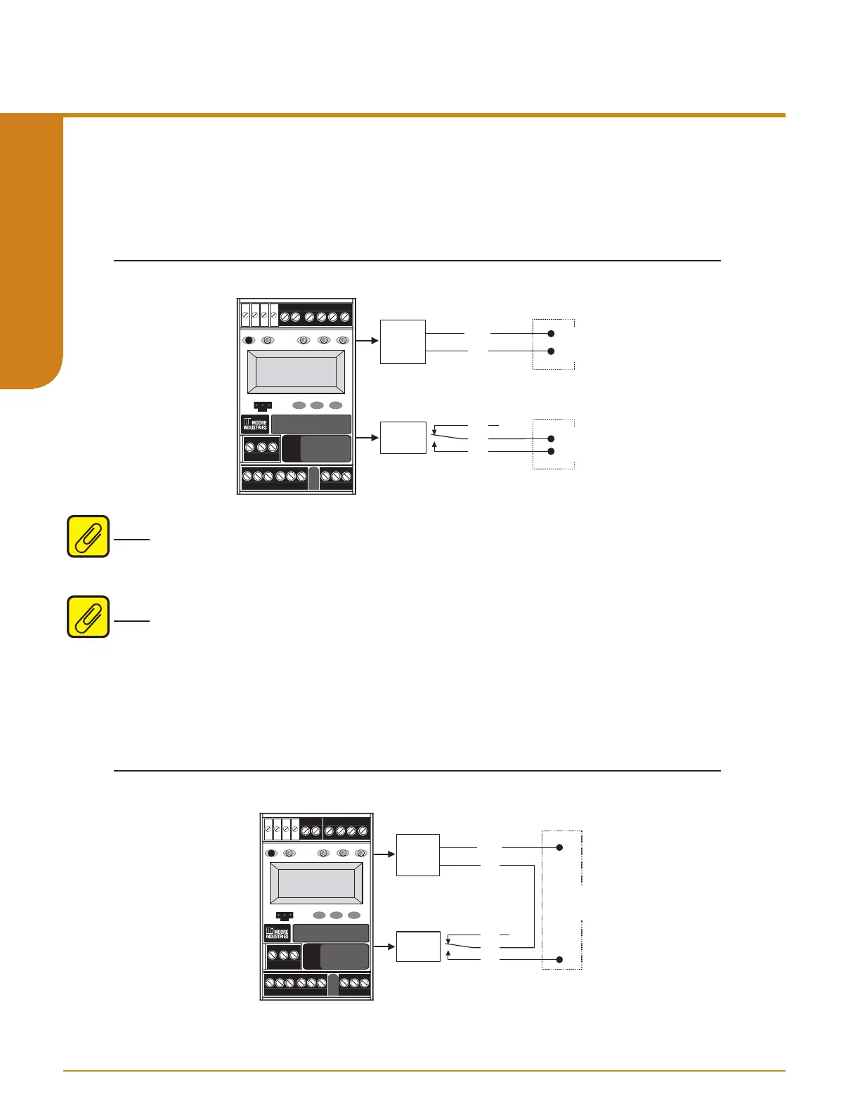
Analog Output in the Safety Path
When the Analog Output is used in the safety path, the fault alarm must also be monitored to
detect STA failures. In Figure 8.4 below, the fault alarm is wired separately in a high availability
architecture. The fault alarm can also be wired in series with the Analog Output to provide a high
integrity architecture.
Figure 8.4. The STA with Analog Output (AO) in the Safety Path
Tx or I+
COM
NC3
CM3
NO3
Analog
Output
Fault
Relay
LOADLOAD
READY
INPUT TRIP 1 TRIP 2
FAULT
SELECT
DOWN
UP
COM
STA
SAFETY
TRIP
ALARM
TAG
126.39
DEG C
Note: When power is lost the AO will fail low. For this reason in a safety application, the logic
solver must be either congured to detect a ‘fail low’ condition (anything less than 4.0mA is
detected as a fault) or ‘fail windowed’ condition (anything outside the 4-20mA range is detected
as a fault).
Note: For STA units with V1.3 rmware or greater, the AO can be used in the safety path.
High Integrity Analog Output
The conguration shown in Figure 8.5. oers the highest AO integrity. Any input or STA fault will
drive the AO signal out of range. However this conguration is vulnerable to spurious trips as
STA safe failures will also drive the AO signal out of range.
Figure 8.5. High Integrity Analog Output example
Tx or I+
COM
NC3
CM3
NO3
Analog
Output
Fault
Relay
LOAD
READY
INPUT TRIP 1 TRIP 2
FAULT
SELECT
DOWN
UP
COM
STA
SAFETY
TRIP
ALARM
TAG
126.39
DEG C